01908 6998020845 899 4400 | 01908 699802Tel 01908 699802
Silver Soldering Stainless Steel

Silver Soldering Stainless Steel, whilst doable, is tricky!
The biggest challenge with Silver Soldering Stainless Steel is the heat needed to melt the solder is close to the temperature at which the Chrome in the Stainless burns (Blueing).
If you get blueing, you will not get Silver Solder to take to it and will have to stop, clean off the blueing and start again!
I would strongly suggest using an Oxygen + Fuel Torch, rather than Fuel + Air as it’s best to get the job to temperature as quickly as possible to minimise the risk of oxides forming.
This can be Oxy/Acetylene, Oxy/Propane or Oxy/Polypropylene (MAPP). All will be hot enough!
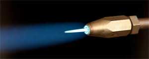
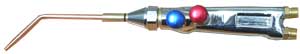
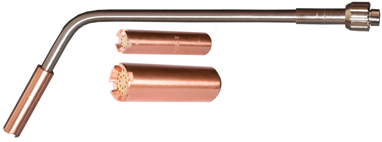
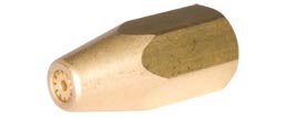
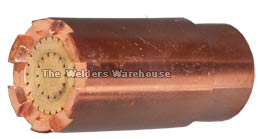
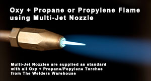
Multi-Jet Nozzle
Technique
- I usually make a small amount of Silver Solder Flux into paste by adding a little water.
- I then put this paste along the edge of the joint.
- As you heat the joint up, the paste initially dries out.
- Just before the joint reaches the melting point of the Silver Solder, the flux will turn into a liquid.
- At this point you should be VERY careful with your flame, try not to keep it still as this will overheat a small area, potentially causing “Blueing”.
- Start testing the heat of the joint by trying to add Silver Solder, do not put the Silver Solder under the flame and remove straight away if it doesn’t melt.
- Once the Silver Solder melts, try not to heat the joint any further and only keep the flame on the joint if necessary.
Conclusions
- Silver Soldering Stainless Steel is tricky, but not impossible
- Practicing on some scrap would be wise!
- I would not attempt Silver soldering Stainless Steel with a Fuel/Air Torch, I would only use an Oxygen/Fuel Torch.
- Care and patience will win the day 🙂
I hope you found this blog article about Silver Soldering Stainless Steel useful.
Please let me know what you thought of this article by leaving a comment.
Don’t worry, your email address won’t be added to a database or shared and you won’t receive any unsolicited email.
Cheers
Graham
Lead Welding
Lead Welding (also known as Lead Burning), is predominantly carried out in the Roofing Industry.
Lead Welding Equipment
Most of the equipment used for Lead Welding (Lead Burning), is the same as regular Gas Welding Equipment, but with a couple of crucial differences:
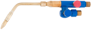
- A Model O Torch is used as this produces the very small flame needed for Lead Welding
- Low Pressure Regulators (especially the Oxygen Regulator), to cope with the very low Gas Pressures needed for the Model O Gun
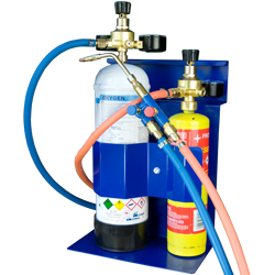
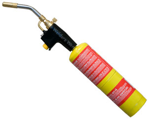
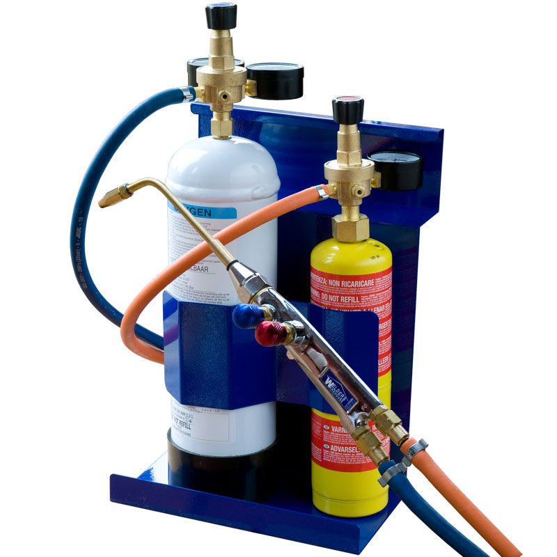
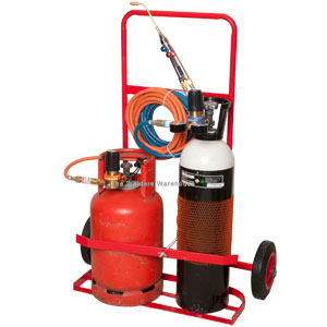
Small Lead Welding Kit
Whilst larger, refillable cylinder kits are still the most popular set up for professional roofers, small, disposable cylinder kits are increasing in popularity. Small kits are great for those who only Lead Weld occasionally, or where small jobs are frequent. It can be frustrating having to get a larger, heavy kit out of the van when only a 30mm weld needs doing. Small kits can be great for nipping up a ladder for such jobs.
Gas for Lead Welding
Traditionally, Oxygen + Acetylene has been the gas combo of choice. However, Acetylene has become more difficult to get, and more expensive! Additionally, some commercial sites will not allow Acetylene on site as it’s considered too dangerous. This is especially prevalent in London as the London Fire Brigade HATE Acetylene!
Alternative Gases for Lead Welding
Oxygen + Propane is a viable option, provided the correct Model O Nozzle is used. The only real downside to Oxygen + Propane (at time of writing), is the lack of a Portapack size Cylinder Trolley available for small cylinders of Oxygen + Propane. This is because Propane Cylinders are shorter and greater in diameter than Oxygen, so they don’t go together on a trolley very well.
Oxygen + Polypropylene is a more viable option, provided the correct Model O Nozzle is used, as a standard Oxy/Acetylene Portapack Trolley will accommodate a 10 litre size Polypropylene cylinder.
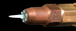
Model O Nozzle for Oxygen + Propane or Polypropylene
Oxygen + Acetylene Nozzles do not work well with liquefied gases such as Propane and Polypropylene because liquefied gases have a much slower burn rate. This makes it difficult to light the Torch as it’s easy to blow the flame out when Oxygen is added.
Our ProJet Nozzles have been specially designed to overcome this problem and are easy to light, even in windy conditions, and provide a small, stable flame.
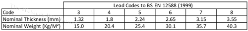
Lead Codes
Lead Thickness is shown as a “Code”. Common Codes are Code 4, Code 5, Code 6 etc.
Following is a Chart of the most common Lead Codes. Chart shows Nominal Lead Thickness and Nominal Weight of each Code.
Conclusions
The correct Lead Welding (Lead Burning) equipment is essential for getting good results.
Whilst Oxygen + Acetylene are the traditional gasses used, Oxygen + Propane or Polypropylene are well worth considering.
I hope you found this blog article useful.
Please let me know what you thought by leaving a comment.
Don’t worry, your email address won’t be added to a database or shared and you won’t receive any unsolicited email.
Cheers
Graham
If you would like to learn how to Lead Weld try contacting the Lead Sheet Academy or NCTS
Stick Welders
Stick Welders come in two basic types, Transformer or Inverter.
Transformer Stick Welders

Whilst not always the case, the vast majority of Transformer Stick Welders have a moving shunt Transformer, meaning you wind a big knob on the front of the machine to adjust power output.
The advantage of a Transformer is they’re cheap. Sadly, that’s about the ONLY advantage!
Moving Shunt Transformer stick welders are:
- Heavy
- Have an AC (Alternating Current) Output. This makes the arc a little fierce and more prone to spatter!
- Can be difficult to Strike an Arc with.
- When Arc striking, it’s easy to stick the rod to the job and can be hard to release it!
- Significant changes to the Power Output will require a significant amount of turning of the moving shunt control knob.
- Transformers tend to overheat quite quickly and take a long time to cool down, especially if they’re not fan cooled!
It should be noted that from 1st Jan 2024 it will no longer be allowable to manufacture Transformer based welders in the UK or EU. It will also no longer be allowable to import Transformer based welders.
Inverter Stick Welders
Inverter Stick Welders, are quite a bit different!

Operationally, the BIG difference is that power is adjusted by turning a knob on the control panel. This is as easy as adjusting the volume of a radio, so significant changes to power output can be made in a Second!
The only real downside to an Inverter is they’re a bit more expensive. But apart from that it’s all positives:
- Inverters are typically around 1/4 of the weight OR LESS!
- DC (Direct Current Output) gives you a softer, smoother arc with less spatter.
- Our Inverter Stick Welders feature “Hot Start”, this gives you around 20% more power for around 1/4 second, making it MUCH easier to strike an arc without sticking the rod to the job!
- Our Inverter Stick Welders also have an “Anti Stick” feature. This immediately cuts the welding power if it senses the rod has stuck to the job. This makes releasing the rod very easy!
- Inverters are electrically a lot more efficient, so they take a lot longer to get hot. In the unlikely event one of our Inverter Stick Welders overheated, cool down is fast because of Fan Cooling.
As a fringe benefit, Inverter Stick Welders can be used for Scratch Start Tig Welding (with an appropriate Tig Torch). Now I’m not a big fan of Scratch Start Tig, but if you’re on a tight budget and would like to get into Tig in a small way, it can be a way forward.
Note however, that Stick Welding Inverters can’t be used for Tig Welding Aluminium!
Conclusion
It’s a bit of a No Brainer really!
Unless you really want to spend as little as possible and you don’t mind the many compromises, an Inverter Stick Welder is the way to go!
Visit our web page for Inverter Stick Welders
I hope you found this blog article useful.
Please let me know what you thought of this article by leaving a comment.
Don’t worry, your email address won’t be added to a database or shared and you won’t receive any unsolicited email.
Cheers
Graham

How Many Welding Rods are in a Box
I get asked “how many welding rods are in a box”, a lot! So I guessed it was about time I published some figures!
There are some variables when it comes to how many welding rods are in a box.
The length of the welding rod is the biggest variable.
Smaller diameter welding rods, eg 1.6mm, 2.0mm & 2.5mm can be 250mm, 300mm or 350mm long.
Larger diameter welding rods can be 350mm or 450mm long.
As welding rods are sold by weight, you will get less longer rods than short.
The following guide to how many rods are in a box shows the number of welding rods per Kg, so you need to multiply this by the weight of the box!
Mild Steel
- 1.6mm (16swg) x 250mm = 153 per Kg
- 2.0mm (14swg) x 300mm = 98 per Kg
- 2.5mm (12swg) x 350mm = 51 per Kg
- 3.2mm (10swg) x 350mm = 32 per Kg
- 4.0mm (8swg) x 450mm = 18 per Kg
- All figures are approximate
View our Range of Mild Steel Welding Rods
Stainless Steel
- 1.6mm (16swg) x 250mm = 129 per Kg
- 2.0mm (14swg)x 300mm = 89 per Kg
- 2.5mm (12swg) x 300mm = 53 per Kg
- 3.2mm (10swg) x 350mm = 30 per Kg
- 4.0mm (8swg) x 350mm = 19 per Kg
- All figures are approximate
View our Range of Stainless Steel Welding Rods
FeNi Cast iron
- 2.5mm (12swg) x 300mm = 60 per Kg
- 3.2mm (10swg) x 350mm = 33 per Kg
- 4.0mm (8swg) x 350mm = 22 per Kg
- All figures are approximate
View our Range of Cast Iron Welding Rods
I hope you found this blog article about “how many welding rods are in a box”, useful.
Please let me know what you thought by leaving a comment.
Don’t worry, your email address won’t be added to a database or shared and you won’t receive any unsolicited email.
Cheers
Graham
How Many Amps for Stick Welding
How Many Amps for Stick Welding, like a lot of things in Welding, is not a precise science because it depends on a number of variables:
- Type of Metal
- Metal Thickness
- Type of Joint
- Joint Preparation
- Welding Rods Diameter
- To some extent, the size of the object being welded
- To some extent, the ambient temperature and the temperature of the metal to be welded
So for example, a Butt Weld in 10mm Steel, with a ‘V’ Prep where a Root run is applied, followed by a Fill and Cap run, will need less Amps than say 5mm thick steel with only a small gap for prep.
Joint Type also has a bearing. A Fillet Joint will need around 10% more Amps than a Butt Joint, while an Outside Corner Joint will need less power than a Butt Joint.
Often the answer comes from testing your best guess at power.
The above variables and comments explain why there is quite a range in the following Amp guides.
6013 Welding Rods for Mild Steel
- 2.0mm = 40-60amps
- 2.5mm = 60-90amps
- 3.2mm = 90-130amps
- 4.0mm = 130-170amps
- 5.0mm = 170-220amps
7018 Welding Rods for Mild Steel
- 2.0mm = 50-70amps
- 2.5mm = 70-100amps
- 3.2mm = 100-140amps
- 4.0mm = 140-190amps
- 5.0mm = 190-240amps
304/316 Stainless Steel Welding Rods
- 2.0mm = 30-50amps
- 2.5mm = 40-70amps
- 3.2mm = 60-90amps
- 4.0mm = 90-120amps
- 5.0mm = 120-170amps
View our Stainless Steel & Cast Iron Rods
Ferro Nickel Rods for Cast Iron
- 2.5mm = 70-100amps
- 3.2mm = 100-130amps
- 4.0mm = 130-150amps
- 5.0mm = 150-170amps
View our Stainless Steel & Cast Iron Rods
Visit our Wires, Rods, Gas Page to view our Range
How Many Amps for Stick Welding – Conclusion
How Many Amps for Stick Welding is, unfortunately, not quite as simple as we might like. There are simply too many variables.
So the easiest way forward is to use the guides above to get you to the right ball park amps, then do a test weld on some scrap metal that’s the same as the job.
I hope you found this blog article about How Many Amps for Stick Welding useful.
Please let me know what you thought by leaving a comment.
Don’t worry, your email address won’t be added to a database or shared and you won’t receive any unsolicited email.
Cheers
Graham
Welding Cast Iron
Welding Cast Iron has quite a few potential pitfalls, but if done correctly, it’s not difficult.
Why is Welding Cast Iron problematic
The key reason why welding cast iron can be problematic is the high carbon content. During the welding process, this carbon migrates into the weld metal and/or the heat affected zone adjacent to the weld metal, causing elevated hardness/brittleness. This is how Cast Iron gets its reputation for post weld cracking.
Process for Welding Cast Iron
Gas Welding heats the Cast Iron slower than Arc based processes and the flame is lower temperature than an arc. This means Carbon migration is not normally a problem. Use of a proprietary Cast iron Gas Welding rod is important. The only real downsides to Gas Welding Cast Iron is the amount of heat needed if components are large. Gas Welding is also a slow process.
Arc/Stick Welding is, arguably, the best all-round process for Welding Cast Iron, provided the correct welding rods are used. Cast iron Welding Rods have a special Graphite rich flux, this graphite chemically ties up the Carbon in the Cast Iron, limiting migration into the weld metal and heat affected zone. There are two common types of Cast iron Welding Rod, Ferro-Nickel and Pure Nickel. Ferro-Nickel are typically 53% Steel and 47% Nickel. Ferro-Nickel Rods are cheaper than pure Nickel and are ideal for welding Cast Iron to Steel. Pure Nickel will produce a softer, more malleable weld deposit. I would advocate using Ferro-Nickel, unless the job specifically requires Pure Nickel.
Mig Welding is, in my opinion, not a great way to weld Cast Iron. Whilst there are specialist Flux Cored Wires available, unless you have a repeating application that you can create a procedure for, I would not advocate Mig Welding Cast iron.
Tig Welding is not considered a suitable process for Welding Cast Iron. An open arc process such as Tig offers no opportunity to mitigate Carbon migration.
Welding Techniques
Gas Welding – There are no specific techniques that need to be deployed.
Arc/Stick Welding – All of the following are important:
- Prep the job with a ‘U’ shaped groove, avoid sharp corners as this can lead to heat build up which will exacerbate carbon migration.
- Use the correct type of welding rod.
- Ensure the component is AT LEAST at room temperature, adding a small amount of pre-heat will help, but you only need the component to be warm to the touch.
- Limit the amount of welding done in one run. As a rule of thumb, do not put down a continuous run that has a length greater than 10x the diameter of the welding rod being used. Having said that, it’s ok to put down multiple runs in different parts of the component (see graphic in next item). Eg, if repairing a 300mm crack with a 3.2mm rod, you can weld a run of 32mm, then do another 32mm run in another part of the crack. Avoid letting the weld area get too hot, this is the purpose of short runs.
- If you’re repairing crack, run a bead across each end of the crack to avoid the crack spreading further.
- Keep the welding rod vertical, not at an angle, like you would for most stick welding.
- Don’t expect to weld cast iron quickly, the key is to take you time and do it properly.
I hope you found this blog article about Welding Cast Iron useful, if things work out well for you, please feel free to post some pictures of your achievements on our Facebook Page
Please let me know what you thought of this article by leaving a comment. Don’t worry, your email address won’t be added to a database or shared and you won’t receive any unsolicited email.
Cheers
Graham
10 Tips to Improve your Tig Welding
1 – Tig Torch Polarity
If you’re welding in DC mode (Steel, Stainless etc), ensure your torch is plugged into the Negative (-) side of your machine’s output. Plugging the torch into the Positive (+) side will cause the Tungsten Electrode to burn away really quickly.
2 – Tig Torch Hold
Make sure you’re in a comfortable position. This is because a big effect on the finished weld is smooth, consistent movement of the torch and so will be a BIG help in your quest to improve your Tig Welding.
If you’re not in a comfortable position, involuntary movement is almost inevitable. Try placing your hand under the torch with the torch sitting between your thumb and second, or third finger. This will allow you to keep your wrist on the job, use your first finger to press the torch trigger.
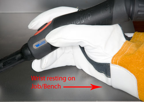
that will help avoid unwanted hand movement
3 – Tig Welding Speed
Moving at the right speed is clearly important, but will vary from job to job. Too fast and you won’t get adequate penetration, too slow and you risk blowing holes or ending up with a large weld.
Moving at a consistent speed will help improve your Tig Welding by producing a nicer looking weld.
4 – Rhythm
Adding Filler Wire to the weld pool at a rhythmic rate will improve the quality and appearance of the weld.
5 – Adding Tig Filler Wire
Don’t add too much filler wire in one go.
Think about a adding Rice to a pan of boiling water, if you throw the whole lot in in one go the pan stops boiling because the Rice has lowered the water temperature.
A weld pool reacts in the same way if you add too much cold filler wire to the molten pool. So add a little often, rhythmically is good and will help improve your Tig Welding.
6 – Correct Tig Tungsten
Ensure you have the correct type of Tungsten Electrode for the material you’re welding. Basic I know, but you’d be surprised how often the wrong tungsten is used.
I tend to go for the Gold type as they can be used for AC or DC applications, so I can’t use the wrong one 🙂
7 – Tig Tungsten Prep
Ensure the Tungsten Electrode is sharpened or prepared for the material you’re going to be welding.
I’ve written a separate article on Tungsten Tig Electrodes which you might find useful.
Go t our Tungsten Electrodes Page
8 – Correct Gas
Ensure you’re using the correct Gas. This is important because the Gas will have a an impact on the finished Tig Weld
In most instances Pure Argon is a good gas to use, although specialist gases are available for specific applications.
9 – Tig Gas Flow Rate
Ensure you have a suitable Gas Flow Rate for the job. Outside Corner joints will need a higher gas flow than a Fillet Weld for example as the gas dissipates more quickly from an Outside Corner Joint.
10 – Tig Filler Metal Selection
Use the right Filler Material for the metal you’re going to be welding. Using Gas Welding Wire for Tig Welding Mild Steel is not a great idea as it is not produced to the same high standards. As a result, contamination problems can compromise the weld.
Tig Welding Wire for Mild Steel is an A15 Type, Gas Welding Wire is an A1.
For Stainless Steel, use a Filler Wire that is either the Same Grade, or a Higher Grade of the same type. For example, to weld 304 Stainless you would use a 308 wire, or the higher 316 grade wire. But to weld 316, you must use 316 wire NOT 308.
Visit our Tig Filler Wire Page.
Visit out Tig Welders Page.
I hope you found this article useful.
Please let me know what you thought of this article by leaving a comment.
Don’t worry, your email address won’t be added to a database or shared and you won’t receive any unsolicited email.
Regards
Graham
Tig Welders
Tig Welders are a great asset for the right applications, but before jumping in to buy one, it’s worth learning a bit about the basics.
TIG, stands for Tungsten Inert Gas
You’ve probably also come accross GTAW which stands for Gas Tungsten Arc Welding. This term is used by the Americans, but the process is the same!

How Tig Welders Work
An arc is struck between a Tungsten Electrode and the workpiece. A weldpool will form under the arc, then the torch is moved along and, if necessary, filler wire is added to the weld pool.
The Weldpool is protected from oxidisation by a Gas Shield (usually pure Argon), which is poured over the weldpool by the Torch.
Although, technically, Tig Welding is very different to Gas Welding, the action, and therefore the skillset, is pretty much the same. So if you have experience of Gas Welding, you should take to Tig Welding like the proverbial Duck to Water!
The upside to Tig Welding is that it’s extremely versatile and affords great control. It’s therefore possible to produce very high quality welds on a range of metals.
The downside with Tig Welding is the process is slow and decent quality equipment is not cheap, although prices have come down in recent Years.
Types of Tig Welder
Tig Welders fall into 3 basic categories:
- DC Output Lift or Scratch Start (cannot weld Aluminium)
- DC Output with High Frequency Start (cannot weld Aluminium)
- AC/DC Output with High Frequency Start (CAN weld Aluminium)
DC Lift/Scratch Start Tig Welders
These are the least expensive and most basic form of Tig Welder. They are usually a DC Arc Welder, or an extra Mode on an Inverter Mig Welder.
To strike an Arc, the Tungsten Electrode is touched down onto the job then lifted off to form a welding arc (much the same as MMA welding).
The limitation of such a Tig Welder is that the tungsten electrode will try to stick to the workpiece when it is touched down and the Tig welders torch is permanently live.
I would only suggest this type of Tig Welding equipment to customers who primarily want to arc, or Mig Weld. For occasional, basic DC Tig Welding however, it’s a viable option.
DC with High Fequency Start
This type of Tig Welder uses a burst of high frequency (HF) to establish the welding arc.
This is easier and more precise than a Scratch start or Lift Tig Welder, as the Tungsten Tig Electrode does not have to be touched down.
A High Frequency (HF) start Tig Welder will usually have additional useful features such as Slope Down and Post Gas Flow.
If you’re seriouse about wanting to Tig Weld, you really should buy a High Frequency Start machine!
AC/DC Tig Welders
AC/DC Tig Welders are the most versatile, usually crammed with professional features and therefore, usually the most expensive.
The key thing about AC/DC Tig Welders is that you can weld Aluminium. This is not possible with a DC only Tig Welder because you need an AC output to weld Aluminium and its alloys.
Tig Welder Control Features
Slope Up/Down
Slope Up is where the Tig Welder starts the welding arc at a very low current, then smoothly brings the welding power up to the level set by the operator.
Some Tig Welders have a pre set Slope Up time that cannot be adjusted, some have manual control that allow different Slope Up times to be set.
Slope down works in the same way but at the end of the weld. When the torch trigger is released, the Tig Welder will fade the power down, instead of stopping it suddenly.
Stopping a Tig Welder arc suddenly can cause the centre of the weld to sink (known as “Cratering”). This phenomenon can even lead to a pin hole in the end of the weld. Fading the Tig Welders arc allows the weld pool to solidify more slowly to avoid Cratering.
Pre/Post Welding Gas Flow
Pre Gas Flow is where the Tig Welder turns on the gas before the arc. This ensures a good welding gas shield.
Post Gas Flow is where the Tig Welder keeps the welding gas flowing after the arc has extinguished. This is important as it prevents the hot tungsten electrode and the end of the weld from oxidising as it cools.
Pulse Welding
A Tig Welder with Pulse control allows the operator to weld very thin material with a little more control.
The principle is that the Tig Welder emits a burst of higher power to achieve penetration. The burst of High Power is followed by a burst of lower power to prevent blow through.
Pulse welding can also be used to achieve penetration on thicker material whilst at the same time, limiting weld size.
AC Frequency Control
An AC/DC Tig Welder may have AC Frequency Control.
AC frequency is the speed at which the polarity of the Tig Welding Torch switches from positive to negative and is measured in Hz (Switches per second).
A Tig Welder with fixed frequency usually switches at around 70 – 100Hz.
A Tig Welder with variable frequency control will typically have a range of around 50 – 250Hz.
The effect the frequency has is to “focus” the Tig Welding arc, in the same way you would focus a torch beam.
The higher the frequency, the more focused the welding arc.
Higher frequency would normally be used to gain greater penetration on thick aluminium, repairing a crack in a casting for example. Lower frequency would be used on thinner sheet aluminium where the heat of the welding arc needs to be spread more to avoid blow through.
Tig Welder Control Panels can look quite complex on first sight. But they are not as intimidating as they look, in fact, most are quite intuitive.
Conclusions
Tig Welders have come down a lot in price in recent Years. Yet at the same time, the level of sophistication has gone up!
Given there is a big price difference between DC only and AC/DC output machines, the first place to start is to ask yourself the question:
Do I need/want to weld Aluminium?
To weld Aluminium, you will need to buy an AC/DC Tig Welder. If not, you can buy a DC only Tig Welder.
If you’re going to buy a DC Tig Welder, my heartfelt opinion would be to buy a High Frequency Start machine.
Visit our Tig Welders Page to view our current range.
If you also want a Mig, then a machine like one of our Synergic iMigs are a great choice. These have a mode for Lift/Scratch Start Tig (with optional Torch). But HF Start Tig is always going to be a better if you plan on doing a fair bit of Tig Welding.
I hope you found this blog article about Tig Welders useful. If you did;
Please let me know what you thought by leaving a comment.
Don’t worry, your email address won’t be added to a database or shared and you won’t receive any unsolicited email.
Cheers
Graham
Can you Tig Weld without Gas
Simply put, NO, you can’t Tig weld without Gas!
Gas is required to protect both the Tungsten Electrode and the weld pool from Oxygen. Most Tig Welder torches are also cooled by the gas, so not using gas would risk burning out the Torch.
It’s theoretically possible to use a Flux, in the same way as Gas Brazing, but this would leave the Tungsten Electrode unprotected from Oxygen, so it would go black and burn away REALLY quickly. Plus, as previously mentioned, you risk overheating a gas cooled torch.
So sorry, but you need Gas to Tig Weld properly!
For most Tig Welding Applications, Pure Argon Gas is ideal, although more exotic (and expensive), gases are available for specific applications.
View our Disposable Pure Argon Gas Cylinder
You might also find my article Can you use the same Gas for Mig and Tig useful.
Conclusion
Can you Tig Weld without Gas – NO
I hope you found this article answering the question “can you Tig Weld without gas” useful, if a little short 😀
Please let me know what you thought of this article by leaving a comment.
Don’t worry, your email address won’t be added to a database or shared and you won’t receive any unsolicited email.
Regards
Graham
Tungsten Tig Electrodes
The choice of type and diameter of Tungsten Tig Electrodes is important as it’s from the Tungsten Tig Electrode that the Arc is struck.
Also important is how the Tungsten Tig Electrode is sharpened when used for DC Tig Welding.
Types of Tungsten Tig Electrode
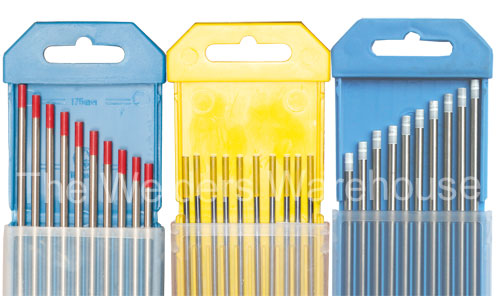
Tungsten Tig Electrodes are colour coded, making them easy to identify.
- Gold = 1.5% Lanthanated Multi Type Tungsten Tig Electrode. Can be used pretty much any material in AC or DC output. These are the only Tungsten Tig Electrodes we stock as they are the most versatile.
- Red = 2% Thoriated. Use for Tig Welding Mild Steel and Stainless Steel.
- White = Zirconiated. Use for Tig Welding Aluminium.
- Grey = Ceriated. Use on most metals AC or DC output (I prefer Gold type).
- Green = Pure. Use for Aluminium & Magnesium
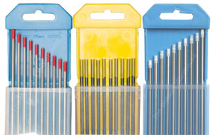
There are a few other types of Tungsten, but the above covers most.
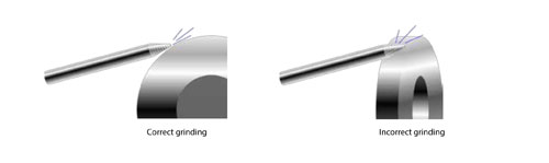
Sharpening
Tungsten Tig Electrodes only need to be sharpened when used in DC output Tig Welding applications.
How the Tungsten Tig Electrode is sharpened is important.
There are different opinions on the exact shape of the point, but my preferred profile is to have a point that’s sharpened to a sharp point that looks a bit like a sharpened pencil.
A good guide is to make the length of the point 2½ times the diameter of the Tungsten. So a 1.6mm diameter Tungsten should have a point around 4.0mm long (1.6 x 2.5 = 4.0). A 2.4mm Tungsten should have a point around 6.0mm long (2.4 x 2.5 = 6.0).
It’s important that grinding lines run along the length of the Tungsten NEVER around the point as this can cause arc instability.
NB – Always wear suitable respiratory protection when grinding.
AC Welding and Tig Tungsten Electrodes
If you’re intending to Tig weld with an AC output, Aluminium for example, there’s no need to sharpen the Tungsten.
Having said that, it’s a good idea to put a small chamfer on the end of the Tungsten.
Once you start welding the end of the Tungsten will form into a dome.
IMPORTANT – If the dome on the end becomes a ball that is larger in diameter than the Tungsten itself, you need to use a larger Tungsten!
How much of a Tig Tungsten Electrode should stick out
There’s no straightforward answer to this one as it depends on a number of factors.
As a general rule, I would have around 5-6mm of the Tungsten sticking out of the Ceramic Gas Shroud.
The important thing is that gas shield integrity around the arc is maintained. So if, for example, you’re welding into a corner, or into a blind hole, good gas shield integrity is easy to maintain, so a greater Tungsten stick out is possible.
If you need to increase Tungsten stick out, to be able to see easily for example, but this increases the risk of poor gas shield integrity, it would be necessary to increase the gas flow to compensate.
Conclusion
The correct choice of Tungsten Tig Electrode is important and will affect the possible results of Tig Welding, as will the way a Tungsten is sharpened if being used for DC applications.
I hope you found this article useful.
Please let me know what you thought of this article by leaving a comment. Don’t worry, your email address won’t be added to a database or shared and you won’t receive any unsolicited email.
Regards
Graham
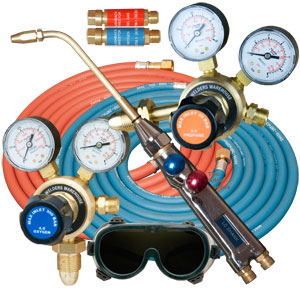
Oxy Acetylene Kits
Oxy Acetylene Kits are one of the oldest types of equipment for welding, but they can do so much more!
But before we talk about that!
What’s important
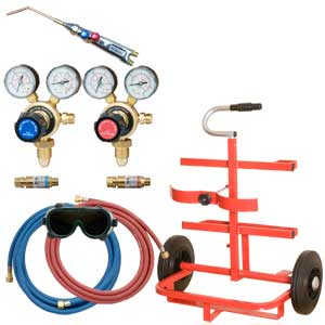
- Safety – Oxygen and Acetylene Kits can be dangerous as both gases dangerous. So it’s critically important that good quality equipment is used, kept in good condition, and inspected/tested at least once a Year.
- Choose the right Kit for your application. If you buy a kit with a Lightweight Torch when you want to do heavy stuff, you’re going to be disappointed. Similarly, if you buy a kit with a Heavy Duty Torch and your application is small and requires a lot of torch manipulation, you’re going to find a Heavy Duty Torch cumbersome. So think about your work and consider the pros & cons. You might find this video useful.
- If you’re making up, or refurbishing your own kit from purchased parts, ensure you have Flash Arrestors (a legal requirement in the UK). Also ensure your hoses have Check Valves on the Torch end.
- When assembling an Oxy Acetylene Kit NEVER use thread sealing products. Also, DO NOT over tighten fittings, seals are made either by an ‘O’ Ring or a Brass on Brass seal which can be damaged by over tightening.
- Ensure your Kit is assembled correctly.
- Ensure you operate your Oxy Acetylene Kit correctly, especially regarding Regulator operation and pressures along with lighting and shutting down the Torch.
View our range of Oxy Acetylene Kits
Uses for Oxy Acetylene Kits
As I indicated at the top, Oxy Acetylene Kits are extremely versatile and have many uses, in my opinion, it’s the most versatile of the Welding processes.
Oxy Acetylene Welding
Oxygen + Acetylene is the only readily available gas combination that can be realistically used for fusion welding and is the main reason engineers buy an Oxy Acetylene Kit.
View our Range of Oxy Acetylene Welding Torches
Brazing/Silver Soldering
With a good quality Torch, Oxygen + Acetylene produces a very precise, hot flame which can be applied very accurately, making it ideal for Braze and Silver Solder applications.
Oxy Acetylene Cutting
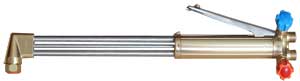
A high temperature flame offers fast heating to cutting temperature.
View our 18/90 Oxy Acetylene Cutting Gun
Heating
Using a Nozzle with multiple jets results in fast, accurate heating, whatever the application.
Conclusion
With all this versatility it’s no wonder an Oxy Acetylene Kit can be found in almost every professional workshop, whatever the trade.
Need to Know More?
If you would like to know more, or would like to discuss what equipment might best suit your needs, please don’t hesitate to get in touch, you can write via our Contact Us page, or phone and ask for me! (numbers at the top of this page)
I hope you found this useful, if things work out well for you, please feel free to post some pictures of your achievements on our Facebook Page
Please let me know what you thought of this article by leaving a comment. Don’t worry, your email address won’t be added to a database or shared and you won’t receive any unsolicited email.
Cheers
Graham
Setting up Oxy Acetylene Kit
Setting up Oxy Acetylene Kit is not rocket science, but it is important to do it correctly.
All the following also applies to Oxy Propane and Oxy Propylene Kits
Setting up Oxy Acetylene Kit – the basics
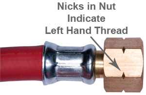
- Oxy Acetylene fittings consist of a concave Female sealing face on one component and a Male ball shaped sealing face on the other. A Nut clamps these faces together to form a gas tight seal.
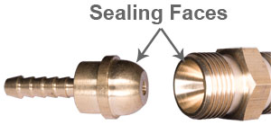
- Threads are not designed to be gas tight as gas will not come into contact with the threads.
- NEVER use PTFE tape or any other form of thread sealing product when setting up gas equipment.
- DO NOT over tighten joints, they only need to be nipped up, take special care if you’re using a large adjustable spanner as it’s easy to over tighten nuts if you’re using a spanner that was designed for use on the Forth Bridge assembly 🙂
- Combustible Gas fittings (Propane, Acetylene etc) will be LEFT HAND THREADS, this will be indicated by little nicks in the corners off the nuts.
Setting up Oxy Acetylene Kit
- Visually check the inside of the thread and seat of the Gas Cylinder outlet, you’re looking for dust, debris or scratches on female sealing face.
- Fit the Gas Regulator to the Gas Cylinder
- Fit the Flash Arrestor to the Regulator – Note, in North America, Flash Arrestors are fitted to the Torch, but here in Europe we fit them to the Regulator.
- Fit The Hose to the Flash Arrestor. Note, it may be that both ends of your hose are the same size nut, allowing the hose to be fitted the wrong way round. The Torch end has a Check Valve (one way valve), if the hose is fitted the wrong way around, you will not get any gas out! Look at both ends of the hose, if the nuts are the same size, look behind the nut, if there is 5-10mm of brass bar between the back of the nut and the start of the hose, that will be the Check Valve and thus the Torch end of the hose.
- Fit your Gas Gun to the end of the Hose.
Setting Gas Pressures
- Check the valves on the Torch are closed.
- Check the Control Knobs on the Regulators are unscrewed to the point where they’re loose and a little floppy.
- SLOWLY open the Gas Cylinder Valves.
- Open the Torch Oxygen Valve 1/4 – 1/2 a turn (no gas will come out yet).
- Screw the Oxygen Regulator Control Knob Clockwise until you feel it start to go stiff. Continue turning while watching the Delivery Pressure Gauge on the Regulator. Continue turning the Regulator Control Knob until the desired pressure is reached.
- Turn OFF the Torch Valve.
- Repeat steps 4-6 with the fuel gas.
- Check all joints for leaks with a proprietary leak detector product.
Lighting Oxy Acetylene (or Propane/Polypropylene) Torch
- Imagine the Torch Gas Control Knob is the face of a clock. Open the fuel gas Torch Valve around 5 minutes.
- Light the gas with a Spark Lighter (Cigarette lighters should be avoided as they can be dangerous)
- Slowly open the Oxygen Torch Valve until the desired flame is achieved.
You’re now ready to get stuck into the job! Always remember to use eye protection, even if you choose not to wear darkened goggles, you should at least wear clear goggles, as there is always a risk of sparks.
Shutting off the Flame
When you’ve finished the job:
- Turn off the Fuel Gas
- Turn off the Oxygen
- Be careful where you put the Torch as it is likely to be hot
End of Work Shutdown of Kit
- Close the Cylinder Valves
- Open the Fuel Gas Valve on your Torch until the Gauges on your Regulator drop to Zero, then close the Torch Valve again
- Repeat step 2 with the Oxygen Torch Valve
- Unscrew the Control Knobs on the Regulators until they go loose and slightly floppy
I hope you found this blog article about setting up Oxy Acetylene Kit useful, if things work out well for you, please feel free to post some pictures of your achievements on our Facebook Page
View our range of Oxy Acetylene Kits
Please let me know what you thought of this article by leaving a comment. Don’t worry, your email address won’t be added to a database or shared and you won’t receive any unsolicited email.
Cheers
Graham
Choosing Welding Gas Regulators
All compressed gases are dangerous, some more than others, so the correctly choosing Welding Gas Regulators is essential.
Gas Regulator Construction
Gas Regulators vary in construction, depending on the gas they’re intended for. Probably the most obvious difference is the screw threads.
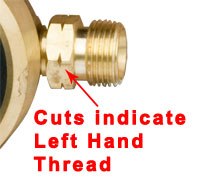
Regulators for combustible gases (Acetylene, Propane, Propylene etc), usually have Left Hand Threads. The left hand thread is indicated by little cuts in the flats of the Hexagon.
Regulators for non combustible gases (Oxygen, Argon, Co2 etc), usually have Right hand Threads and as such do not have the cuts on the Hexagon.
Another important difference can be the material used to manufacture internal components.
For example, internal Acetylene Regulator components are manufactured from different material to Propane Regulators. It’s therefore important that the correct regulator is used as failure to do so can be extremely dangerous.
In the example outlined above, Propane will corrode the internal components of an Acetylene Regulator, inevitably leading to failure and leaking!
So when choosing welding gas regulators, ALWAYS select the correct regulator for the gas!
Single Stage v Multi Stage Regulators
I’ve written a separate article on the Difference between Single and Multi Stage Regulators
I’ve also produced a Video
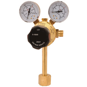
Oxygen Gas Regulators
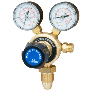
The most common type of Oxygen Regulator has a 0-10 bar outlet. However, as Gas Welding Torches typically only require around 0.2 bar, a Regulator capable of delivering up to 10 bar is going to be difficult to adjust accurately at such a low pressure.
To overcome this, 0-4 bar Oxygen Regulators are also available. These are much easier to adjust at the low pressures required for most Gas Welding & Brazing torches. Even Cutting Guns can be used with nozzles up to 1/16″.
0-10 bar are for where larger Nozzles are going to be used.
I would also recommend not considering an Oxygen or Argon regulator with less than a 300 bar input rating as 300 bar cylinders are becoming more common and are likely to become the norm in future.
Acetylene Gas Regulator
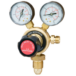
Acetylene becomes unstable and explosive if compressed to a high pressure. Because of this, Acetylene is dissolved in a special material.
Because of the low pressure nature of Acetylene cylinders, the Gas Regulator for Acetylene has a different internal set up.
Most Acetylene Regulators have a maximum delivery pressure of 1.5 bar.
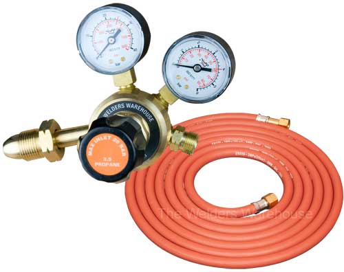
Propane Gas Regulators
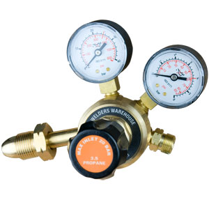
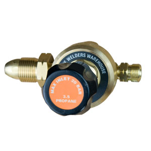
Propane Regulators are commonly supplied with, or without gauges.
As discussed earlier, Acetylene and Propane Regulators should never be used with any other gas than that which they are designed for, although Propane Regulators can be used for Propylene, which is made up of around 50% Propane.
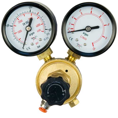
Argon and Argon/Co2 Gas Regulator
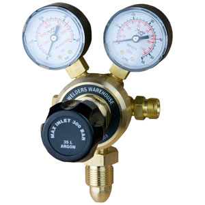
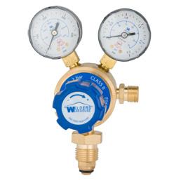
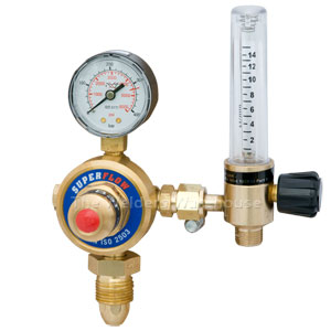
Argon Gas Regulators are much the same as Oxygen Regulators. However, a key thing to look out for is the Delivery Gauge (usually on the Right).
On an Oxygen Regulator the delivery Gauge normally shows Pressure in Psi and Bar. Argon Regulators normally show Gas Flow Rate in Litres Per Minute and Cubic Feet Per Hour.
It’s important to make sure the Delivery Gauge reads Flow Rate as most Mig and Tig Welders will quote a recommended delivery in Litres per Minute.
An Argon Regulator should also be used for Argon/Co2 Mixed gases.
CO2 Gas Regulator
Most of a Co2 Regulator is the same as an Argon Regulator.
The one BIG difference is the Cylinder Fitting, which is Female.
All the other Regulators we have discussed have a Male thread to go into a Female Fitting on the cylinder. Co2 Cylinders have a Male thread, so the Regulator has to have a Female fitting.
Gas Regulators for Disposable Gas Cylinders
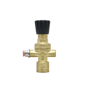
Regulators for Disposable Gas Cylinders do the same job as their refillable cylinder counterparts, except the fitting onto the Cylinder is completely different.
Disposable Cylinders are filled to a lower pressure.
For these reasons, Disposable Cylinder Regulators are not compatible with refillable cylinders.
Regulators for use with Disposable Cylinder can have no Gauges, 1 Gauge or 2 Gauges.
Conclusions
Correctly choosing welding gas regulators is important as pressurised gas cylinders can be dangerous.
But as long as care is taken to choose good quality and the right specification/type for the gas you’re going to be using, all should be well.
I hope you’ve found this article useful, you can find more Gas Equipment related information in our Knowledge Zone and in other articles of my blog.
Please let me know what you thought of this article by leaving a comment. Don’t worry, your email address won’t be added to a database or shared and you won’t receive any unsolicited email.
Cheers
Graham
Whats the difference between Single Stage and Multi Stage Regulators
As some of you may prefer to watch rather than read, I’ve also produced a VIDEO on this subject.
Single Stage Regulators
A Single Stage Regulator takes Cylinder Pressure and reduces it down to an adjustable pressure output.
For example, in the case of an Oxygen Cylinder, the cylinder pressure of up to 300 bar (4410 psi) is reduced in a single step to the output of 0-4 bar (for example).
The main advantage of a Single Stage Regulator is price. Simply put, they’re cheaper than Multi Stage Regulators.
The downside is Single Stage Regulators have a less stable output, especially at low pressure settings.
Where Single Stage Regulators are used for high output applications, it will be necessary to adjust the pressure from time to time. This is because as the cylinder pressure drops, the output pressure will creep up.
Multi Stage Regulators
A Multi Stage Regulator is a bit like having two Single Stage Regulators in one!
The first, non adjustable stage, reduces Cylinder Pressure to around 10 bar (can be up to 20 bar).
The adjustable 2nd stage is used to deliver the output pressure required by the operator.
This means when you adjust the Regulator, you are only dropping the pressure from between 10 or 20 bar to your desired output pressure. Not up to 300 bar down to desired output pressure!
Multi Stage Regulators offers two key advantages over Single Stage Regulators.
Multi Stage Regulator Output pressure is more stable.
Reducing cylinder pressure in 2 steps results in greater output pressure stability and consistency. Stable, Consistent output pressure is especially important where a very low pressure is required – very small flame torches for example.
Secondly, where high gas consumption is used, the delivery pressure is more consistent over the life of the cylinder. This is because as cylinder pressure drops, a Single Stage Regulator will gradually deliver a higher and higher gas pressure. This will necessitate regular adjustment to maintain delivery pressure.
A Multi Stage Regulator offers much more consistent output pressure because the depleting cylinder pressure has little effect on the adjustable second stage.
How to tell the difference between Single & Multi Stage Regulators
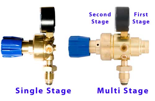
From the front, Single Stage and Multi Stage Regulators look very similar.
But you can see from the above image, a Multi Stage Regulator has the 1st Stage protruding from the rear. This is the most obvious visual difference between the two types!
Conclusions
If you need your Gas Regulators to be cheap, Single Stage Regulators are likely to be your best choice.
If consistency of delivery pressure during high gas consumption applications is important to you, Multi Stage Regulators are likely to be a better choice.
If you use micro torches (Model ‘O’ or Little Torch for example), the greater outlet pressure stability of Multi Stage Regulators will be a significant advantage for you.
I hope you found this blog article about the difference between Single Stage and Multi Stage Regulators useful.
View our range of Gas Regulators
Please let me know what you thought of this article by leaving a comment.
Don’t worry, your email address won’t be added to a database or shared and you won’t receive any unsolicited email.
Cheers
Graham
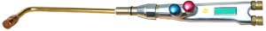
Lightweight vs Heavy Duty Torches
I’ve also produced a video on this subject
I regularly get asked “Lightweight vs Heavy Duty Torches, what’s the difference?”
There is a common perception the Heavy Duty Torches are better quality in some way, this is not the case!
In fact with our Torches, both types are constructed in exactly the same way, the difference is physical size, weight and available accessories
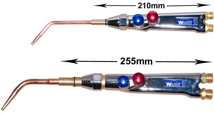
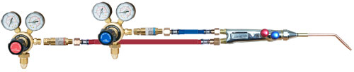
The Torches above are Oxy/Acetylene variants, but apart from the Neck/Nozzle, Oxy/Propane (Propylene) variants are the same!
At this point I shall point out that if you prefer to learn via Video, I have produced a video version of this article called Lightweight v Heavy Duty Gas Torches
Apart from the size difference that you can see in the above photo, the other two main differences are:
- The Heavy Duty is physically heavier than the Lightweight (clues in the names 😀)
- The Input fitting that your Hoses will fit onto are different:
- Lightweight has 1/4″BSP Threads
- Heavy Duty has 3/8″BSP Threads
- (I’ve written a separate article about BSP Threads)
Lightweight Torch Accessories
The Welders Warehouse Lightweight Torch comes with 4 Welding/Brazing Nozzles where the Oxy/Acetylene variant is chosen. 3 of our superb Multi-Jet Brazing Nozzles are supplied with the Oxy/Propane (Propylene) variant.
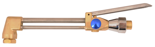
Lightweight Cutting Attachment
A Cutting Attachment that’s capable of cutting up to around 20mm steel is available. This can be used with Oxygen/Acetylene.
There is currently not a Lightweight Cutting Nozzle available for Oxygen/Propane (or Propylene), although the Oxy/Acetylene Cutting Nozzle, while not ideal, is usable.
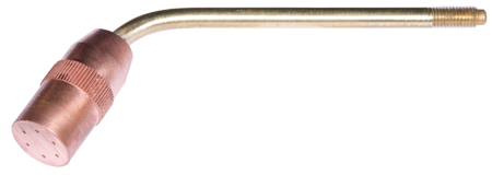
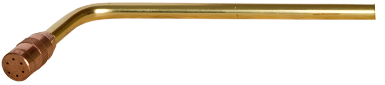
Lightweight Heating Neck/Nozzle
The Welders Warehouse developed this Nozzle/Neck assembly for the HVAC industry (Heating, Ventilation, Air Conditioning), where it’s used for brazing 3 1/4″ Copper Pipe. Having said that, it’s ideal for anyone needing a bit more heat as it has 6 flame jets. This also makes it popular with Model Engineers needing to braze large components on model steam locomotives!
This versatile Heating Nozzle can be used with either Oxygen/Acetylene or Oxygen/Propane (Propylene)
Heavy Duty Torch Accessories
As with the Lightweight Torch, The Welders Warehouse Heavy Duty Torch comes with:
- 4 Welding/Brazing Nozzles where the Oxy/Acetylene variant is chosen
- 3 of our superb Multi-Jet Brazing Nozzles where the Oxy/Propane (Propylene) variant is chosen
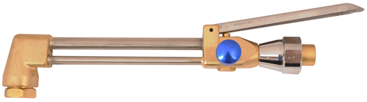
Heavy Duty Cutting Attachment
A Cutting Attachment that’s capable of cutting from around 3mm – 150mm Steel is available. This can be used with Oxygen/Acetylene or Oxygen/Propane (Propylene), when the correct Nozzle type is used.
Heavy Duty Heating Nozzle/Neck (Oxygen/Acetylene)
Heating Nozzle & Neck for Oxygen/Acetylene provides 6 flame jets for rapid heating.
Heavy Duty Heating Nozzle/Neck (Oxygen/Propane)
Heating Nozzle & Neck for Oxygen/Propane (Propylene) comes with two Nozzles for rapid heating.
Conclusions
I titled this article “Lightweight vs Heavy Duty Torches”, but in reality, they’re not really competing with each other as both have their merits!
The advantage with the Lightweight is that, well it’s lighter! This means you’re going to be able to hold it for longer without becoming fatigued.
The Lightweight Torch also uses smaller bore hoses, these are both lighter and offer better flexibility.
So the key advantage of the Lightweight Torch is it’s lighter and offers better overall dexterity!
The downside is the Lightweight Torch is not quite as versatile because there are a smaller range of accessories available.
The key advantage of the Heavy Duty is its versatility, because of the greater range of available accessories.
Thicker steels can be cut with either Oxy/Acetylene or Oxy/Propane (Propylene).
Higher output Heating Nozzles are also available.
Downside is a heavier torch will make fatigue more likely and the need for larger bore hoses to handle the gas requirements of the larger accessories means the hoses are less flexible.
So greater versatility comes at the cost of dexterity!
I hope you found this Lightweight vs Heavy Duty Torches useful. If you would like to know more before you make a decision, please feel free to call and ask for me (number’s at the top of the page).
Please let me know what you thought of this article by leaving a comment.
Don’t worry, your email address won’t be added to a database or shared and you won’t receive any unsolicited email.
Regards
Graham
Setting up a Gas Regulator
How you use your Gas Regulator will have a direct impact on long term life and accuracy.
Incorrect use of a Gas Regulator and incorrect storage are the two most common reasons for Gas Regulator failure, or the delivery gauge becoming inaccurate.

Putting Gas Equipment together
When putting Gas Equipment together, including fitting the Gas Regulator onto the Cylinder, it’s important to:
NOT use any kind of thread sealer (ptfe tape etc). Gas Equipment threads do not seal at the thread and using thread sealer will most likely cause leaks and can be dangerous.
NOT to over tighten any of the fittings. Fittings only need to be nipped up with a short spanner. Heaving on a spanner, especially a long spanner, will almost certainly lead to damage of the sealing surface causing leaks.
I’ve written a separate article about Setting Up Gas Equipment
Setting Gas Delivery Pressure or Flow Rate
You should refer to your equipment for the amount of gas required to operate it.
Mig and Tig Welders will normally specify a Flow Rate in Litres Per Minute (LPM).
Gas Welding and Cutting Equipment will normally specify a Pressure in PSI or Bar.
When you first fit your Gas Regulator to the Cylinder the cylinder will obviously be OFF. The following list explains delivery Flow Rate/Pressure setting (if using two gases, do one gas at a time). Carry out procedure in a well ventilated area with no combustion sources if the gas is flammable.
Ensure the Gas Regulator Control Knob (big Black Knob with Blue Cap in the picture), is unscrewed to the point where it is loose and floppy.
Slowly open the Cylinder Valve to turn the Gas ON. Note the Contents Gauge Needle pops up to show the pressure in the cylinder.
DO NOT open the Cylinder Valve with the Gas Regulator Control Knob screwed in as this may damage the Delivery Gauge. Manufacturers will not warranty replace parts damaged by this sort of incorrect use.
Open your Gas Torch Control Valve ½ turn (note no gas will come out at this time). If your setting gas flow on a Mig or Tig, operate the machine so it’s gas valve is open.
Slowly turn the Gas Regulator Control Knob clockwise. When you start to feel resistance the gas should start to flow and the Delivery Gauge Needle will start to move around the scale. Continue to turn the Control Knob until the desired Flow Rate/Pressure is reached.
Close the Gas Torch Valve or shut off the Mig/Tig Welder so gs no longer flows.
Note that when gas is no longer flowing the Delivery Gauge Needle will creep above the value set. This is quite normal and will go back down once gas starts to flow again.
Closing Down your Equipment for the Day
Closing down your equipment correctly is as important to its long term reliability and accuracy as the set up. Follow these simple steps (if using two gases, do the following for each gas separately):
Turn the Cylinder Valve OFF
Open your Gas Torch Control Valve or activate Mig/Tig Welder, so gas flows, note how the Delivery Gauge and Cylinder Contents Gauge Needles drop to Zero.
Unscrew the Gas Regulator Control Knob until it goes loose and floppy.
Close the torch Control Valve or deactivate the Mig/Tig Welder.
Storing Gas Regulator
If you don’t intend using your Gas Regulator for a Month or more, it’s a good idea to apply just a small amount of pressure to the internal valve, to stop it from sticking.
Do this by slowly screwing the Control Knob clockwise until you just feel resistance, then screw it one quarter turn further.
Remember to unscrew the Control Knob bar to loose and floppy before fitting to a pressurised gas cylinder.
Well I hope you found that informative and useful. More information on Gas Equipment can be found within this blog, or in our Knowledge Zone.
Please let me know what you thought of this article by leaving a comment. Don’t worry, your email address won’t be added to a database or shared and you won’t receive any unsolicited email.
Cheers
Graham
Oxy Acetylene Flame
An Oxy Acetylene Flame will fall loosely into one of three types:
Neutral, Oxidising and Carburising
Neutral Oxy Acetylene Flame
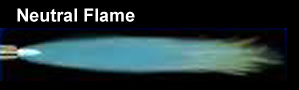
A Neutral flame is achieved when there are equal amounts of Oxygen and Acetylene.
A Neutral Flame is so named because it has no chemical effect on the molten metal.
Key characteristics of a Neutral Flame are a defined Cone Flame at the base of a long feather flame. If the correct size of nozzle is being used a Neutral flame should produce no more than a gentle hiss.
A Neutral Oxy Acetylene Flame is used for Welding, Brazing and Silver Soldering most metals and is therefore the most common type of flame to use. A Neutral Flame is also used for Oxy Acetylene Cutting.
Oxidising Oxy Acetylene Flame
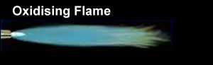
An Oxidising Flame is where there is more Oxygen than Acetylene used.
Key characteristics of an Oxidising Flame are a small, sharp, more pointed looking Cone Flame at the base of a shorter feather flame. An Oxidising Flame will have a distinct roar.
Use of a slightly Oxidising flame is more specialised, typical uses are for welding copper and zinc based metals or manganese steels. In these cases an oxidising flame creates base metal oxide that protects the base metal.
Carburising Oxy Acetylene Flame
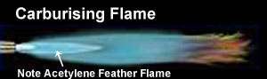
A Carburising Flame is where there is more Acetylene than Oxygen used.
Key characteristics of a Carburising Flame is a secondary feather flame, caused by the excess Acetylene burning further down the flame length. If the correct size of nozzle is being used a Carburising flame should produce no more than a gentle hiss.
Use of a Carburising Flame is more specialised, typical uses are for welding lead, surface hardening processes or welding high carbon steels.
I hope you found this blog article useful, if things work out well for you, please feel free to post some pictures of your achievements on our Facebook Page
Please let me know what you thought of this article by leaving a comment. Don’t worry, your email address won’t be added to a database or shared and you won’t receive any unsolicited email.
Cheers
Graham
Gas Nozzle Pressures
The correct Gas Pressures are important. Incorrect pressure can increase the risk of Flashback and make Flame Adjustment difficult.
The following Guides should help you
Lightweight & Heavy Duty Swagged Oxy/Acet Gas Welding Nozzles
Lightweight include DH type Oxy Acetylene Nozzles (not pictured)
Heavy Duty includes type 3, 4 & 5 Torches
Nozzle Size – Gas Nozzle Pressures
- No1 – Metal Thickness = 1.0mm – Oxy/Acet Pressures = 0.15bar each
- No3 – Metal Thickness = 2.0mm – Oxy/Acet Pressures = 0.15bar each
- No5 – Metal Thickness = 2.5mm – Oxy/Acet Pressures = 0.15bar each
- No7 – Metal Thickness = 3.2mm – Oxy/Acet Pressures = 0.15bar each
- No10 – Metal Thickness = 4.0mm – Oxy/Acet Pressures = 0.20bar each
- No13 – Metal Thickness = 5.0mm – Oxy/Acet Pressures = 0.30bar each
- No18 – Metal Thickness = 6.5mm – Oxy/Acet Pressures = 0.40bar each
Multi-Jet Oxy Propane/Propylene Nozzles
Nozzle Size – Gas Nozzle Pressures
- No1 – Metal Thickness = 1.0mm – Oxy/Prop Pressures = 0.20bar each
- No3 – Metal Thickness = 2.0mm – Oxy/Prop Pressures = 0.20bar each
- No5 – Metal Thickness = 3.0mm – Oxy/Prop Pressures = 0.25bar each
- No7 – Metal Thickness = 4.0mm – Oxy/Prop Pressures = 0.25bar each
AHT Heating Nozzles
Nozzle Size – Gas Nozzle Pressures
- AHT25 Oxy/Fuel Pressures = 0.30bar each
- AHT50 Oxy/Fuel Pressures = 0.40bar each
- AHT100 Oxy/Fuel Pressures = 0.70bar each
Oxy/Propane Super Heating Nozzles
Nozzle Size – Gas Nozzle Pressures
- 1H Oxy Pressure = 0.7-2.0bar + Propane Pressure = 0.15-0.5bar
- 2H Oxy Pressure = 0.7-2.0bar + Propane Pressure = 0.15-0.5bar
- 3H Oxy Pressure = 1.8-5.0bar + Propane Pressure = 0.3-1.1bar
- 4H Oxy Pressure = 1.8-5.0bar + Propane Pressure = 0.30-1.1bar
Oxy/Acetylene (ANM) Cutting Nozzles
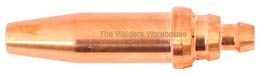
Nozzle Size – Gas Nozzle Pressures
- 1/32″ Cuts 3-6mm Steel – Pressures = Oxy 1.5bar / Acet 0.15bar
- 3/64″ Cuts 5-12mm Steel – Pressures = Oxy 2.0bar / Acet 0.15bar
- 1/16″ Cuts 10-75mm Steel – Pressures = Oxy 2.5-3.5bar / Acet 0.20bar
- 5/64″ Cuts 70-100mm Steel – Pressures = Oxy 3.0bar / Acet 0.30bar
- 3/32″ Cuts 90-150mm Steel – Pressures = Oxy 3.0bar / Acet 0.30bar
- 1/8″ Cuts 150-300mm Steel – Pressures = Oxy 4.5bar / Acet 0.35bar
Oxy/Propane (PNM) Cutting Nozzles
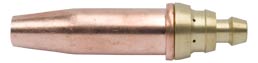
Nozzle Size – Gas Nozzle Pressures
- 1/32″ Cuts 3-6mm Steel – Pressures = Oxy 1.5bar / Prop 0.15bar
- 3/64″ Cuts 5-12mm Steel – Pressures = Oxy 2.5bar / Prop 0.15bar
- 1/16″ Cuts 10-75mm Steel – Pressures = Oxy 3.0-3.5bar / Prop 0.20-0.35bar
- 5/64″ Cuts 70-100mm Steel – Pressures = Oxy 3.5bar / Prop 0.4bar
- 3/32″ Cuts 90-150mm Steel – Pressures = Oxy 4.0bar / Prop 0.4bar
- 1/8″ Cuts 150-300mm Steel – Pressures = Oxy 5.5bar / Prop 0.6bar
I hope you found this blog article about Gas Pressures useful.
Please let me know what you thought by leaving a comment.
Don’t worry, your email address won’t be added to a database or shared and you won’t receive any unsolicited email.
Cheers
Graham
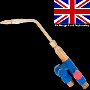
Model O Torch
Model O – a little bit of History
We’ve been selling the original Model O Torch for some Years now. It’s always been a popular torch, especially among Roofers, who use it for Lead Welding and LOVE the feel of the torch and the precise flame adjustment that can be achieved.
Now, after over 30 Years of the above model O, we’ve updated the design to incorporate some tweaks that customers have expressed a desire for.
Model O – the Next Generation
The first thing to say is we haven’t changed much! After all, if a Torch is as popular as the Model O it would be stupid to re-invent the proverbial wheel 🙂
So what have we changed?
We’ve now made the Oxygen Inlet from a single forged piece of Brass, rather than two pieces brazed together. This increases the strength and durability of the whole Torch, plus improves Oxygen Gas Flow.
We’ve tweaked the geometry of the valves to provide even better and more precise flame adjustment.
We’ve increased the angle of the Neck Bend as LOADS of customers, old and new, told us the angle on the old torch wasn’t tight enough.
Model O Nozzles
The original Model ‘O’ Nozzles are designed for Oxy/Acetylene or Oxy/Hydrogen.
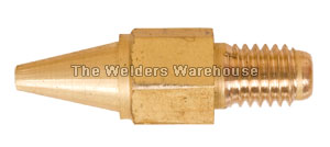
These original Model O Nozzles are VERY small. They’re numbered 1-5 with 5 being the biggest. Having said “Biggest” it’s worth noting that the number 5 is only slightly bigger than a conventional torch No1. So the term “Biggest” is somewhat subjective!
The most popular Oxy/Acetylene Nozzle is the No3, which Roofers use for Code 4 Lead Welding. Although all the nozzles sizes are popular.
No1 nozzle produces such a tiny flame I’m pretty sure you could weld a KitKat wrapper with it 🙂
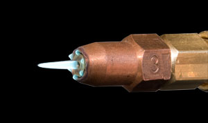
Oxy Propane/Propylene Nozzles
Launched in 2020, our Pro-Jet dedicated Oxy/Propane or Propylene Nozzles.
These feature a small ring of tiny nozzles, surrounding a central main flame. The purpose of this design is to allow the greater volume of fuel gas that’s necessary for liquefied gases, to flow and burn efficiently.
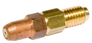
Pro-Jet Nozzles are available in numbers 1, 2 & 3. (3 being the biggest).
Customer feedback has been excellent, with Roofers telling us the No1 nozzle is ideal for Code 4 Lead.
Using the standard Oxy/Acetylene Nozzles for Oxy Propane or Propylene is ok, but the torch is difficult to light and the flame blows out REALLY easily. This is because Propane and Propylene are liquifed gases that burn a lot slower than Acetylene.
Pro-Jet Nozzles overcome these problems and are much easier to light, especially in windy conditions!
Using the Model O
The single biggest problem that customers report with using their Model O Lead Welding Torch is difficulties with flame adjustment. This usually means the flame blows out too easily when lighting, or the flame pattern changing on its own.
In 95% of cases, this is caused by too much gas pressure being set on the Regulator. When customers report problems and we ask what pressure they have set, we invariably get figures around 1.0 to 1.5 bar. The correct pressure is between 0.15 and 0.2 bar!!!! This is barely off the Zero Pin of a Regulator!
Gas Regulator Selection
The problem of setting too higher Gas Pressure derives from one of two things
The operator thinks that 1.0 – 1.5 bar is the correct pressure IT IS NOT!
The operator has a 0-10bar Oxygen Regulator. Trying to set a STABLE pressure of between 0.15 and 0.2bar on a Regulator with up to 10bar of pressure is virtually impossible!!!
Here at The Welders Warehouse, we offer a 0-4bar Oxygen Regulator for lower pressure applications, which is actually MOST applications! A 0-4bar Oxygen Regulator is far better for setting and maintaining the stable low pressure needed for using a Model O Lead Welding Torch. A 0-4bar Oxygen Regulator is suitable for most Welding and Light Cutting Torches. A higher output Oxygen Regulator would only be necessary for Cutting Nozzles above 5/64″.
All our “Standard” Oxy Acetylene and Oxy Propane/Propylene kits are supplied with the 0-4bar Oxygen Regulator.
Even More Low Pressure Control
For even more control, we also offer a 0-2bar Multi Stage Regulator. This Regulator comes with or “Premium” Oxy Acetylene Kits
I’ve written a separate article on the difference between Single and Multi Stage Regulators
I’ve also produced a Video
Lighting a Model ‘O’ Torch
There is no real difference between lighting Model ‘O’ Torch to lighting any other kind of Oxy Acetylene Torch. It’s just more important to make sure the gas pressure on the Regulators is set correctly and only turning the Torch Valves by very small amounts at a time. The key thing to remember is that with such small nozzles, small changes can make a big difference, so changes have to be made gradually.
Conclusion
The Model O Torch is still the first choice for Lead Welders and the new Torch fine tunes all the things Lead Welders loved about the original. As long as the Oxy Acetylene Kit is set up correctly, the new Model O will provide Years of trouble free Lead Welding.
Visit our Model O page, where you will find prices and can order.
I hope you found this blog article useful, if things work out well for you, please feel free to post some pictures of your achievements on our Facebook Page
Please let me know what you thought of this article by leaving a comment. Don’t worry, your email address won’t be added to a database or shared and you won’t receive any unsolicited email.
Cheers
Graham
Can I weld with a Propane Torch
I get asked “Can I weld with a Propane Torch”, a lot.
Sadly, the simple answer is NO, you need Oxygen and Acetylene to Fusion Weld.
Its not about heat because you can melt steel with Oxy/Propane
A lot of companies are now offering Propylene as an alternative to Acetylene. Oxy/Propylene is a lot hotter than Oxy/Propane but you still can’t successfully weld with it.
Oxygen + Acetylene produces a strong, malleable weld. Oxygen and Propane or Propylene will produce a hard brittle weld.
Why can’t you weld with Propane?
I confess I don’t fully understand the Chemistry that goes on (Chemistry was never my thing), but it involves “Redox Reaction”.
The simple way it was explained to me, by someone who does know about it, is that there is transfer of Electrons between an Oxygen+Acetylene Flame and Hydrogen atoms that are present in an Oxygen+Acetylene Flame. This is a Redox Reaction.
As there are no, or a lot less, Hydrogen Atoms in an Oxygen+Propane or Polypropylene flame, Redox Reaction takes place with the metal in the molten weld pool, Oxidising the molten metal.
The resulting weld is brittle, weak and cracks or breaks easily.
You can read more about the Redox Reaction via these websites:
Wikipedia BBC Bitesize and Chemistry LibreText or search”Redox Reaction on your favourite search engine!
I’ve read on some websites and forums that the Carbon atoms that part make up Acetylene (Acetylene is 2 atoms of Carbon + 2 atoms of Hydrogen, C2H2) combines with the Oxygen to form Co2 and that this acts as a shielding gas (a bit like Mig).
I find this implausible as Propane has 3 atoms of carbon, so why wouldn’t the same thing happen?
Anyway, I’m not overly bothered about the science because if it were possible to overcome the fact that you can’t produce acceptably strong welds with Oxygen + Propane/Propylene, someone would have done it and taken on the VAST Global Acetylene market.
What can you use Oxy/Propane for?
The good news is that you can do pretty much everything else with Oxygen + Propane or Propylene. Assuming you have the right Torch or Kit.
Heating, Cutting, Brazing and Silver Soldering are all easy to carry out with Oxy/Propane.
A Word of Warning
You MUST NOT use an Acetylene Regulator, Acetylene Flash Arrestor or Acetylene Hose with Propane or Propylene. Propane and Propylene will corrode internal parts of Acetylene equipment, making it dangerous!!!!
I personally would not use Propane or Propylene with a Gas and Air Torch, except for soft soldering.
Gas/Air torches produce a reasonable amount of heat, but it is not very concentrated or focused and the significantly lower flame temperature means it can take too long to get the job to Brazing or Silver Solder temperature, thus allowing oxides to form.
Can I weld with a Propane Torch Conclusion
“Can I weld with a Propane Torch”, NO! Harsh, but true 😀 However, with the correct equipment, you can do pretty much everything else.
Visit our Propane Torch page.
I hope this blog article useful, even if it din’t give you the answer you were hoping for.
Please let me know what you thought of this article by leaving a comment.
Don’t worry, your email address won’t be added to a database or shared and you won’t receive any unsolicited email.
Cheers
Graham
Can I use Propane or Propylene instead of Acetylene
I take a lot of calls regarding using Oxygen + Propane or Oxygen + Propylene instead of Acetylene + Oxygen.
Well the short answer to the Title question is, “Yes” and “No”.
Sorry its ambiguous, but it all depends what you want to do! Let me explain!
Fuel Gas Options
Oxygen + Fuel Gas kits used to be simple, you had Oxygen + Acetylene! However, the waters are now muddied by a number of factors.
- Acetylene can be hard, and expensive, to obtain.
- Cylinder Rental for Acetylene Cylinders has shot up in price.
- Acetylene often rings alarm bells with Health & Safety conscious officials because of its combustibility and unstable nature!
Unfortunately, Oxy/Acetylene is still the best all purpose gas combo, but there are viable alternatives, as long as you know what you want to be able to do and you choose carefully.
Oxy Propane

Propane is the easiest fuel gas alternative to Acetylene to obtain and is normally supplied in cylinders on a Deposit basis, rather than rented (as is usually the case with Acetylene).
For most users, Propane works out cheaper, especially for infrequent users of Oxygen + Fuel kits. The only real downside to using Oxy/Propane is that it can’t be used for actual Welding. Oxygen and Propane fuelled kits are however, ideal for Silver Solder, Brazing, Cutting and Heating. So as long as you don’t want to Weld, Oxygen and Propane is a great way to go! Oxygen + Propane produces a flame temperature of around 1800⁰C.
Oxy Propylene
Propylene is a blend of gases, including Propane and available in a number of throwaway canister Brands, Gasex, Mapp & Turbo Gas to name but three, it’s also available in larger, refillable cylinders. An Oxygen/Propylene mix burns quite a bit hotter than Oxygen and Propane, typically around 3100⁰C and could, therefore, be considered better as jobs will reach operating temperature quicker.
Unfortunately, like Propane, Propylene is not suitable for fusion welding. You will find people out there who will tell you it can be used to weld, but in tests that I’ve carried out, the welds it’s produced have been fairly brittle, so I certainly would be doing anything structural or that my Life depended on with it!!!
Oxygen + Propylene is however excellent for Silver Solder, Brazing & Heating.
Oxygen + Propane equipment should also be used for Oxygen + Propylene.
The Welders Warehouse offers a number of excellent Kits, please take a look at our Oxy Propane/Propylene Kits Page to see the range!
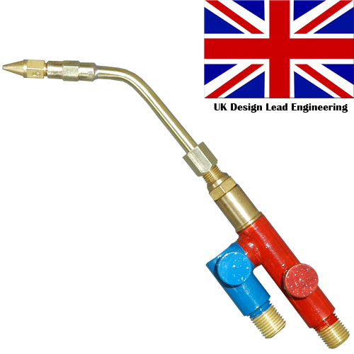
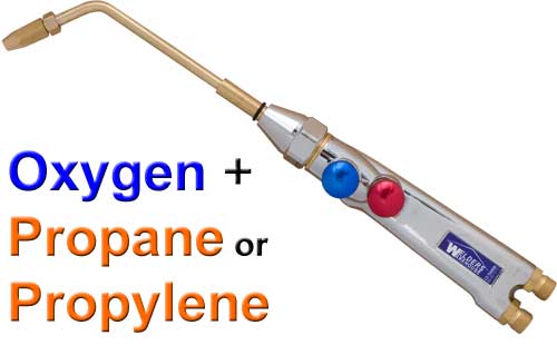
Oxy Propane/Propylene Torch
Whilst a standard Oxy Acetylene Torch can be used for Oxy Propane/Propylene, it’s far from ideal. Propane & Propylene are slower burning gases.
Propane & Propylene also travel through the system as a vapour, not a gas, not actually turning into a gas until they meet air.
The Welders Warehouse has developed two special Multi-Jet Torches for Oxygen + Propane & Propylene.
Lightweight Oxy Propane/Propylene Torch
Heavy Duty Oxy Propane/Propylene Torch
Both use our own, specially designed Multi-Jet Nozzle, which is a lot easier to light and a less likely to blow out, compared to an Oxy/Acetylene Nozzle.
Conclusions
With the right equipment, Propane or Propylene, when mixed with Oxygen, are a viable alternative to Oxy Acetylene for most applications, except fusion welding.
Hope you found this article useful.
You might also find my article “Swapping from Oxy Acetylene to Oxy Propane or Propylene” useful.
Please let me know what you thought of this article by leaving a comment. Don’t worry, your email address won’t be added to a database or shared and you won’t receive any unsolicited email.
Cheers
Graham
Swapping from Acetylene to Propane or Propylene
I’ve already written an article Titled Can I use Propane or Propylene Instead of Acetylene so I won’t go over that ground again here.
Instead I want to concentrate on the equipment differences and what you need to change when swapping from Oxy Acetylene to Oxy Propane or Propylene.
Gas Welding Equipment
OK, so you already have an Oxygen Regulator, Flash Arrestor and Hose, along with a Torch. There’s no reason why you can’t continue to use these, although there is another option that I’ll come to later!
Here’s the rub, you CANNOT use Acetylene Equipment for Propane or Propylene! Sorry about that, but the internal materials are different and Propane will corrode the internal materials that Acetylene equipment is made of (Propylene is around 50% Propane).
So swapping from Oxy Acetylene to Oxy Propane or Propylene will require some new Gas Equipment.
The least you’ll need
- You WILL need to change your Acetylene Regulator to a Propane type (including for Propylene).
- You WILL need to change your Acetylene Hose to a Propane Hose (including for Propylene).
- You will need to check the label on your Flash Arrestor, if it says “Fuel”, it’s OK to use with Propane & Propylene. If it says “Acetylene” you will need to change it for a “Fuel” type.
- Your Torch SHOULD be OK for Acetylene, Propane or Propylene, ours certainly are, but if in doubt, you should check with the manufacturer. DON’T TAKE RISKS WITH GAS!!!!
Another Option
Now I mentioned earlier that there was another option.
Depending on the condition of your Oxy Acetylene kit, you may find it doesn’t cost a great deal extra to sell your existing kit (as a complete kit), then buy a complete NEW Oxy Propane/Propylene Kit.
The advantages of this option are:
- You have all new kit, with a warranty
- You’re not mixing old kit with new
Other Benefits
If you buy a new kit from The Welders Warehouse, you’ll not only get a Propane Regulator with Gauges (most have no gauges), but you’ll also get one of our EXCELLENT, purpose designed Multi-Jet Torches.
Relevant Product Options
View our range of Oxy Propane or Propylene Kits
View our Range of Hoses
View our Propane/Propylene Regulator
View our Fuel Flash Arrestor
View our Oxy Propane/Propylene Torches
I hope you found this blog article about swapping from Oxy Acetylene to Oxy Propane or Propylene useful.
Please let me know what you thought of this article by leaving a comment.
Don’t worry, your email address won’t be added to a database or shared and you won’t receive any unsolicited email.
Cheers
Graham
Propane
Is Propane any good?
YES! It’s a great gas!
- It’s versatile
- Can be used with or without Oxygen (with correct Torch)
- It’s cheap, compared to Acetylene
- It’s readily available
- It’s available without Cylinder Rental
The only real downside to Propane is that you can’t weld with it.
Pretty much everything else can be done.
With the right Torch, Oxy/Propane is great for Heating, Brazing, Silver Soldering etc.
How Propane Works in practice
Propane is a liquified gas and is stored in a cylinder with a void above the liquid.
The Liquid turns into a vapour, which fills the void until a certain pressure is reached, this pressure will depend on ambient temperature. The colder the cylinder/liquid is, the lower the vapour pressure will be.
It is the vapour that is drawn off and travels through the Regulator, Flash Arrestor, Hose and Torch, until it meets air. When the vapour meets air it turns into a gas, which then burns.
As vapour is drawn from the cylinder, more liquid turns into vapour, until the cylinder is empty.
Propane Problems
I’ve only ever really spoken to customers about 2 possible problems with Propane.
- In cold conditions, for example, the cylinder is stored in an unheated area during Winter. The temperature of the liquid can drop so low that the Torch/Flame draws vapour off faster than the liquid in the cylinder can become more vapour. This means the flame starts to get smaller and ultimately, goes out, giving the impression that either the cylinder has run out, or the Regulator is faulty, when in fact, neither is the case. The only real solution to this problem is to ensure the cylinder is at room temperature when in use.
- If used with an Oxy/Acetylene Torch, Oxy/Propane tends to spit and fart quite a bit and the flame can easily blow out, especially when lighting. A Torch designed for
- Oxy/Propane will perform FAR better and be much easier to use. Apologies for the shameless plug of our Multi-Jet LD and Multi-Jet HD Oxy/Propane Guns, but they are very, very good! Please watch the video demonstration via the “Video” tab on the pages (same video on both pages).
I hope you found this blog article useful, if things work out well for you, please feel free to post some pictures of your achievements on our Facebook Page
Please let me know what you thought of this article by leaving a comment. Don’t worry, your email address won’t be added to a database or shared and you won’t receive any unsolicited email.
Cheers
Graham
No Rent Gas Cylinders
No Rent Gas Cylinders have become very popular in recent Years. For those who cannot justify the cost of Renting a cylinder, but find disposable cylinders expensive, no rent gas cylinders are perfect.
Rented Gas Cylinders
Renting the Gas Cylinder has always been the traditional way of accessing Industrial type Refillable cylinders.
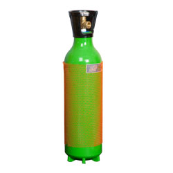
Gas fills are carried out by swapping the empty cylinder for a full one.
You carry on renting the cylinder until you no longer require the Cylinder.
The advantage of Cylinder Renting is larger users of gas needing multiple cylinders, can get big discounts. Therefore, the overall cost of cylinder rental and gas fills for high volume users is competitive.
The downside is that if you only need one or two cylinders and you only need them to be filled occasionally, the costs are high. If you don’t use the cylinder at all for a Month or Two, it’s sitting there costing you money!!
Disposable Gas Cylinders
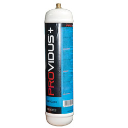
Disposable Gas Cylinders have always been the product of choice for DIY welders as the cost of renting an Industrial type Refillable Cylinder is simply too high.
The advantage of Disposable Gas Cylinders is you only pay for the gas you use as the cylinder is owned by you. Also, Disposable Gas Cylinders are small, light and easy to move around. In fact they will fit straight onto the back of a lot of DIY Mig Welding Machines.
The downside is that they can work out quite expensive if you more than the occasional bit of welding.
No Rent Gas Cylinders
No Rent Gas Cylinders combine the best of both Disposable and Industrial Rented Gas Cylinders.
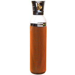
Essentially, you pay a deposit on the Cylinder (typically around £60, depending on the cylinder size), then you pay for the gas fill (typically around £40, depending on the gas).
In my opinion, a 9 litre cylinder is a great choice for DIY welders. 9 litre cylinders contain around 1230 litres of gas (around 11 times a 110bar disposable). Size wise, they are similar to a SCUBA divers cylinder, so easy to store and move around.
A 20 litre cylinder is also readily available. These typically have around 4000 litres of gas, so are more economical, but are bigger and heavier, so perhaps less convenient.
The BIG advantage of No Rent Gas Cylinders for the DIY and low volume Welder is no ongoing rent on the cylinder. So if you don’t use gas for a Month or two, the cylinder is not costing you any money. Also the gas works out MUCH cheaper than Disposable Gas Cylinders.
There are not really any significant downsides to No Rent Gas Cylinders. You will need an Industrial type Gas Regulator, which is an additional cost if you don’t have one.
Also, the upfront cost of No Rent Gas Cylinders is higher than disposables, because of the deposit. But the ongoing savings are so great that it’s hard not being able to justify these upfront costs.
A Word of Warning
There are several companies offering No Rent Gas Cylinders, these include:
Adams Gas, Gas UK, SGS Gases and Hobbyweld.
READ THE TERMS & CONDITIONS!!!!!
At time of writing, only Adams Gas appear to offer a FULL Return of Deposit when you’ve finished with the cylinder and take it back. The other companies appear to keep some, or all of your deposit if you don’t buy a refill within a defined period of time. So once again.
READ THE TERMS & CONDITIONS!!!!!
Conclusion
Gas Cylinder Renting/No Rent/Disposable is a bit of a personal thing because which method is best for you will depend on how often you use Gas, how much gas you use and how portable you need a gas cylinder to be.
The most important thing is to do your research and read T&C’s
The Welders Warehouse offers disposable gas cylinders but we do not offer No Rent Gas Cylinders as we cannot ship them by courier.
I hope you found this blog article useful, if things work out well for you, please feel free to post some pictures of your achievements on our Facebook Page
Please let me know what you thought of this article by leaving a comment. Don’t worry, your email address won’t be added to a database or shared and you won’t receive any unsolicited email.
Cheers
Graham
BSP Threads
BSP Threads are used for most Oxygen, Acetylene and Propane equipment.
Fuel Gases, Acetylene, Propane, Polypropylene etc will have Left Hand Threads because this stops Fuel Gas and Non Fuel Gas equipment from being mixed up, which is potentially VERY dangerous.
Left Hand Threads will have small cuts machined into the Nut to indicate they are Left hand.
Non Fuel Gases Oxygen, Argon, Argon/Co2 Mix etc, will have Right Hand Threads and so no cut on the Nut.
BSP Thread Sizes
The size of BSP Threads causes a lot of confusion because, for example, a 3/8″BSP Thread is over 1/2″ in diameter!
BSP stands for “British Standard Pipe” and is a very old thread.
In the example of 3/8″BSP, 3/8″ is the diameter of the BORE of the pipe NOT the outside diameter of the thread.
If the BORE of the pipe is 3/8″ diameter, clearly the outside diameter of the pipe has to be greater and it’s this outside pipe diameter that a thread would be cut into. So the Thread diameter has to be greater than the 3/8″ BORE diameter of the pipe!
BSP Thread Diameters
Gas equipment typically uses 4 different BSP Threads, the following is the basic specifications of these threads.
| Size | Outside Diameter | Pitch |
| 1/8″ | 0.383″ (9.73mm) | 28 TPI |
| 1/4″ | 0.518″ (13.16mm) | 19 TPI |
| 3/8″ | 0.656″ (16.66mm) | 19 TPI |
| 5/8″ | 0.902″ (22.91mm) | 14 TPI |
BSP Thread Uses in Gas Equipment
1/8″BSP is commonly used for the outlet thread on small Regulators, the type used for throwaway cylinders for example.
1/4″BSP is typically used on the Torch end of Oxygen, Acetylene & Propane Hoses where small torches, including Lightweight and Model ‘O’, are used.
3/8″BSP is typically used for Regulator Outlets, Flash Arrestor Inlet + Outlet and the Torch end of Hoses where larger Torches, including Heavy Duty and Cutting Torches, are used.
5/8″BSP is typically used for Gas Cylinder Outlet and therefore Regulator Inlet.
I hope you found this article useful.
Visit our Gas Welding Tools & Fittings page.
Please let me know what you thought of this article by leaving a comment.
Don’t worry, your email address won’t be added to a database or shared and you won’t receive any unsolicited email.
Regards
Graham
Gas Regulator Safety
It’s never a good idea to cut corners with Gas Equipment, it’s simply not worth the risk!
Gas Regulator Safety should very much be at the top of anyone’s agenda when buying Gas Equipment.

European Standard EN ISO 2503
First and foremost is checking that an Industrial Gas Regulator is conforms to EN ISO 2503. This is the current European Standard.
Unfortunately, it’s not quite as simple as that, because a lot of manufacturers will “Self Certify”.
Self Certifying by marking the Regulator as “Conforming” to the standard is technically legal, but it means you’re taking their word that it does actually conform. Given most Gas Regulators are manufactured in distant Countries, outside the EU, that’s a big leap of faith!!!
For those of us who supply Industrial Gas Regulators to the end user there is the risk of falling foul of Trades Descriptions legislation.
Bizarrely, it’s OK for a manufacturer (or importer), to supply a Regulator with dubious credentials to a Retailer. But it’s not OK for the Retailer to supply a Regulator that claims to conform to EN ISO 2503, but actually doesn’t, to an end user!
It’s a quirk in the Trades Descriptions rules that Retailers of Gas Regulators need to be aware of!
Why should you care?
It’s important! An industrial Gas Cylinder (Oxygen or Argon for example), has a typical cylinder pressure of 230bar (nearly 3,400 psi). You REALLY don’t want a poor quality Gas Regulator holding that kind of pressure back for you!!!
Even the smaller Non Rent Gas Cylinders that are popular for DIY, have a cylinder pressure of at least 137bar (over 2000 psi).
For perspective, a car tyre is typically inflated to between 2bar and 3bar (around 30psi – 45psi). Now think about the bang and the mess a Tyre makes if it blows and multiply that by a few decibels!!!!
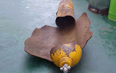
My advice would be to make sure an Industrial Regulator not only conforms to EN ISO 2503 but has been independently verified as conforming by an organisation such as Belgium based Apragaz .
Look for the Apragaz logo stamped or etched on fully verified Gas Regulators:
The seller of any Industrial Gas Regulator worth buying will be able to supply independently verified certification, should you want proof!
Gas Regulator Safety
But it’s not just Gas Regulator Safety that’s at stake here, you also want your Gas Regulator to do it’s job well.
A cheap Regulator may seem a great choice if you “only use it now and again”. However, it’s very frustrating if the outlet pressure fluctuates because of poor design or quality. Cheap Industrial Regulators can also be dangerous if not designed well, or are made from sub standard materials!
Quality = Performance and Reliability
Proven build quality to BS EN 2503 ensures you have a decent Regulator that will work well, be safe and have a good service life.
The difference in cost between a cheap Industrial Gas Regulator and a quality assured Regulator that has been verified as conforming to EN ISO 2503 is not that great. So why take the risk!
The Welders Warehouse own brand Gas Regulators are manufactured by UK Company Wescol.
The Welders Warehouse own brand Gas Regulators are manufactured using the best quality materials, inside and out, including an ALL BRASS Body and Bonnet.
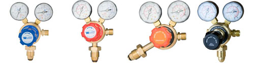
ALL The Welders Warehouse own brand Industrial Gas Regulators are VERIFIED by Apragaz as Conforming to EN ISO 2503.
Conclusions
Gas Regulator Safety is VERY important for avoiding the risk of serious injury, or worse!
Buying Regulators that have been independently verified as conforming to EN ISO 2503 will not only ensure you’re buying a SAFE Gas Regulator, but that you’re also buying a Gas Regulator that will work well and give Years of service.
I hope you found this article about Gas Regulator Safety useful.
Please let me know what you thought by leaving a comment.
Don’t worry, your email address won’t be added to a database or shared and you won’t receive any unsolicited email.
Cheers
Graham
Gas Leaks
Testing for Gas Leaks is important both for obvious safety reasons, but also because, who wants to waste expensive gas?
Testing for Gas Leaks is, however, not as simple as it might seem!
Where Fuel Gases are concerned, these have a distinctive odour, so you can normally smell a leak. Oxygen, Argon and Co2 however, are odourless.
Leak Detector Products
The best way to test for Gas Leaks is with a Leak Detector Spray. If you’re testing for leaks of Acetylene, Argon or Co2, this can be good old fashioned washing up liquid. Something we all have in our kitchens right!
Regular Washing Up liquid should NOT be used for Oxygen as it contains elements that can react with pressurised Oxygen and potentially combust.
When sprayed onto a joint that’s expected to be gas tight, Leak Detector Spray will form bubbles if gas is leaking.
I’ve already mentioned that Regular Washing Up Liquid should not be used with Oxygen, however, there is an exception!
Teepol, a UK Manufacturer, offer a number of products that can be used as a Gas Leak Detector for Oxygen (in addition to their designed for use), for example:
These products don’t contain elements that are potentially hazardous when used with pressurised Oxygen.
The beauty of these products is that you can use them for the purpose they were intended AND as a low cost Gas Leak Detector when you need to!
Leak Detector Spray
If on the other hand, you would prefer a dedicated Leak Detector Spray, well we can help with that!
Generally speaking, there are no joints on Gas Welding Equipment that need any kind of thread seal. Mainly because the threads don’t actually form part of the gas tight seal. But if you do have a joint that requires the thread sealing it is important the right product is used ESPECIALLY for Oxygen!
PTFE tape is one of the most common thread sealing products on the market, but you have to be careful. Regular plumbers PTFE tape is coated with a fine layer of mineral oil. This is potentially combustible if exposed to pressurised Oxygen.
Therefore it’s important to only use an OIL FREE PTFE Tape for Oxygen gas joints!
Although not the most riveting of reads, for those of you who would like to know a little more, here is an extract from MOD document JSP 319.
Conclusions
Clearly, testing for Gas Leaks is a good idea! But using the correct product is also important for safety.
I hope you found this blog article about Gas Leaks and Gas Leak Detection Products useful.
Please let me know what you thought of this article by leaving a comment.
Don’t worry, your email address won’t be added to a database or shared and you won’t receive any unsolicited email.
Cheers
Graham
Plasma Cutters
Plasma Cutters are a fantastic tool. It is, however, important to understand the different types of arc ignition and to be realistic about performance!
I’ve also produced a Video about choosing a Plasma Cutter
How Plasma Cutters Work
Plasma Cutters use compressed air and an electric arc to cut metal.
You can cut just about any metal with a Plasma Cutter, including Mild Steel, Stainless Steel and Aluminium.
Plasma Cutters work by forcing compressed air into a chamber that contains a Plasma Electrode and a Plasma Cutting Tip. As the compressed air is forced into the chamber an electric arc is struck between the Plasma Electrode and Plasma Cutting tip.
This arc “Plasmarises” the compressed air, making it electrically conductive.
This electrically conductive air then escapes the pressurised chamber via a small hole in the Plasma Cutting tip, taking the energy of the arc with it. The heat of the Plasma Arc melts the metal to be cut, while the force of the compressed air blows it away.
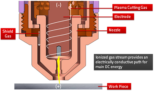
Because the stream of plasmarised air is very narrow and the melted metal is blown away, the Plasma Cutter introduces very little heat into the job, thus there is little, or no, distortion of the job.
Plasma Cutters also offers a big advantage over more traditional cutting methods in that it operates from only one side and can easily cut any shape, even where there is a second panel behind that is to be left intact.
Plasma Arc Ignition
There are two basic forms of Plasma Arc Ignition, High Frequency and Contact Striking.
High Frequency (HF) Arc Ignition
Here, a brief High Frequency arc is used to jump the gap between the Plasma Electrode and Tip. This allows the main arc to form across the HF arc and cutting to start.
Contact Arc Ignition
Here, the Torch Head keeps the Plasma Electrode and Tip in contact with each other, creating a dead short.
When the Torch Trigger is pressed to start Cutting, the machine delivers a small amount of power, at the same time, compressed air is used by a pnuematic piston to pull the Plasma Electrode and Tip apart.
As this happens, the machine delivers full power to start the arc.
This process is much the same as starting an old fashioned Arc Welding Rod, where the rod is touched down and lifted off to start welding!
HF or Contact Arc Start?
Which is the best method of Arc starting depends a lot on how you use a Plasma Cutter.
High Frequency is better for automated (CNC) Plasma Cutting because the often frequent stopping and starting of the Plasma Arc will wear the Torch Head Piston of a Contact Start. HF is also a little faster, so again, better suited to the rapid stop/start cutting of a CNC application.
High Frequency Start does however require additional electronic circuitry. This can be expensive to replace if it fails outside of warranty. There is also a theoretical possibility that HF could cause problems with nearby sensitive electonic devices, or medical items (Pacemakers for example).
Contact Arc Starting is better suited to Hand Plasma Cutting. It’s a simpler system, so there’s less to go wrong. The lack of High Frequency also means Contact Start Plasma Cutters are less likely to cause problems with other electronic or medical devices.
Choosing the right Plasma Cutters
Plasma Cutters are generally selected by cut performance, that is to say how thick they will cut.
Plasma Cutter cut performance is quoted for mild steel. Stainless Steel and Aluminium require more power, so generally, cut performance will be less for these materials.
Typically, a Plasma Cutter that is quoted as having a max cut capacity of 6mm Mild Steel, will cut a max thickness of 5mm Stainless Steel and 3.0mm Aluminium, or around 10% and 50% less than mild steel.
Care has to be taken with manufacturers claims on Plasma Cutters cut capacity; more honest suppliers will quote a “max or Genuine Cut Capacity” and a “Max Sever”.
The “Max or Genuine Cut Capacity”, lets say 6mm, means the Plasma Cutter will cut up to 6mm mild steel, cleanly and at a speed of at least 250mm (10″) per minute.
“Max Sever”, lets say 10mm, is the absolute maximum that the Plasma Cutter will achieve on Mild Steel. However, expect a poor quality cut and VERY slow speed.
Unfortunately, some Plasma Cutter suppliers will say “cuts up to 10mm steel” when the thickness they quote is in fact the Max Sever! It’s “Buyer Beware” I’m afraid!
Obviously, the thinner the metal, the quicker a Plasma Cutter will cut, at a given output power.
As a rule of thumb, I always suggest customers consider a Plasma Cutter with a cut capacity at least 30% greater than they think they will need. That way there’s always spare capacity if required and good cut speed on the planned work.
Plasma Cutters Power Input
Input power requirement is another important factor to consider.
Generally speaking, a Plasma Cutter that has an output of up to 30amps will normally run fine off a 13amp Fused Plug.
However, the most common starting size for a Plasma Cutter is 40amps output! These machines normally require a 16amp power supply to operate at the maximum output.
That having been said, our 40amp Plasma Cutters have an output range that is typically 20-40amps. So can be used at an output that is within a 13amp fuse. In fact our own tests have shown that the Cros-Arc Plasma Cutter works at full power off a 13amp supply, if a Slow Blow (‘T’ type) fuse is used and the arc is not stop/started too quickly.
Conclusions
Plasma Cutters are a great tool, but it’s worth carefully considering your needs before making a purchase.
I hope you found this blog article about Plasma Cutters useful.
Please let me know what you thought by leaving a comment.
Don’t worry, your email address won’t be added to a database or shared and you won’t receive any unsolicited email.
Cheers
Graham
Weld Distortion and Defects
Weld Distortion and defects are an annoying, but unavoidable part of welding. But they can be mitigated!
Porosity
Porosity is where Holes/Bubbles appear in the weld. This is created when gas becomes trapped in the weld pool as it solidifies. Causes include:
- Lack of shielding gas – (Mig/Mag & Tig Welding) INCREASE GAS FLOW.
- Too much shielding gas – (Mig/Mag & Tig Welding). If the flow rate of gas is too high, turbulence is created over the weld. This turbulence allows air to penetrate the gas shield. This then means you don’t have an adequate gas shield around the weld pool. REDUCE GAS FLOW.
- Damp Welding Rods – (MMA). USE DRY WELDING RODS.
- Oil/Grease/Rust etc on the workpiece – As suface contaminates burn off they create excess gas. This gas can then get trapped in the weld, resulting in holes. CLEAN WORKPIECE BEFORE WELDING.
- Surface coating on the workpiece – Paint or plating burning off will create excess gas (same as 4), which then gets trapped in the weld. REMOVE SURFACE COATING BEFORE WELDING.
Poor Welds
- Tall Narrow Welds – Caused by a lack of heat input or travelling too fast. INCREASE POWER or SLOW DOWN.
- Flat Wide Welds – Caused by excessive heat input, or travelling too slowly. REDUCE POWER or SPEED UP.
- Undercut – Caused by excessive heat input. REDUCE WELDING POWER.
- Slag Inclusion – (Arc Welding and Gasless Mig only). Primary cause is slag from a previous weld not being fully removed before second weld pass is overlaid. Undercut will make slag removal more difficult and increase the risk of slag inclusion. REMOVE ALL SLAG PRIOR TO OVERWELDING.
Weld Distortion
Weld Distortion is caused by two factors:
- The general uneven heating of the workpiece that welding causes.
- The weld metal itself shrinking.
The first is impossible to avoid, but can be mitigated:
- Ensure all joints are as tight as possible.
- Use the best process for the job (Mig, Tig MMA etc).
- Use no more welding power than is necessary.
- The idea is to minimise the heat input.
Weld Metal Shrinking is, again, impossible to avoid.
When a weld is created you’re producing a molten pool of metal. Like most materials, this hot metal will be in an expanded state. Thus, as it cools and solidifies, it contracts (or shrinks).
As the weld metal cools and shrinks it pulls on the metal around it, creating stresses and distortion.
Welding Distortion can be corrected by stretching the weld metal to relieve the stress caused by shrinking.
For butt and outside corner welds, this can be done by peening.
Do this by holding a metal block behind the weld and peening evenly along the weld with a hammer.
Be careful to avoid over peening as this will overstretch the weld and re-distort the workpiece, this cannot be corrected easily!!!
So peen the whole weld a little, assess the effect, then if necessary, peen a little more.
Conclusions
Most Weld Distortion and Defects that You’ll encounter can be avoided, simply by preparing properly.
Distortion can be minimised by ensuring metal parts fit tightly together as gaps will mean bigger weld deposits and therefore more weld shrinking!
So a bit of time spent on preparation can minimise the time spent fixing Weld Distortion and Defects after welding!
I hope you found this blog article useful.
Please let me know what you thought by leaving a comment.
Don’t worry, your email address won’t be added to a database or shared and you won’t receive any unsolicited email.
Cheers
Graham
How do I Dispose of Empty Gas Cylinders
“How do I dispose of empty Gas Cylinders” is a question I get asked a lot!
Much will depend on the type of cylinder and the gas contained within it.
Types of Gas Cylinder
Refillable cylinders should always be returned to the supplier for recycling. Given there’s often a deposit on refillable cylinders it makes sound sense to return them.
Disposable cylinders, by their very nature, should be disposed of, but they need to be disposed of responsibly.
Most recycling centres will not take disposable gas cylinders unless it can be proved that they’re empty.
Once it can be conclusively proved that the cylinder is empty, it’s essentially scrap metal and therefore highly recyclable!
Under no circumstances should disposable gas cylinders be put in domestic, or industrial waste bins/bags.
Types of Gas
If the Gas is non flammable (Argon, Co2 Argon/Co2 mix for example), the easiest way to prove they’re empty is to drill a hole in the cylinder, although some recycling centres may require the cylinder be cut in half.
You can do the same with flammable gases (Propylene, Mapp, Propane, Butane, Oxygen for example), but you need to be REALLY CAREFUL not to create sparks or too much heat. Dribbling water on the drill as you use it might be a good idea here.
I hope you found this blog article about “How do I dispose of empty Gas Cylinders” useful. If you did;
Please let me know what you thought by leaving a comment.
Don’t worry, your email address won’t be added to a database or shared and you won’t receive any unsolicited email.
Cheers
Graham
Visit to the Lead Sheet Training Academy
I had a very interesting visit to the Lead Sheet Training Academy recently!
I’ve visited many times before, but this trip was partly to meeting the new Director of Training and Operations, John Lewis.

It was also a good opportunity to touch base with Sharon in the office and Simon, the Academy’s Lead Instructor, both of whom I’ve known for a few Years.
Workshop Setup
The Workshop set up is impressively professional.
They have “Real Rigs” to carry out practical work on, as well as both bench based and portable Lead Welding Equipment (all supplied by us 😀).
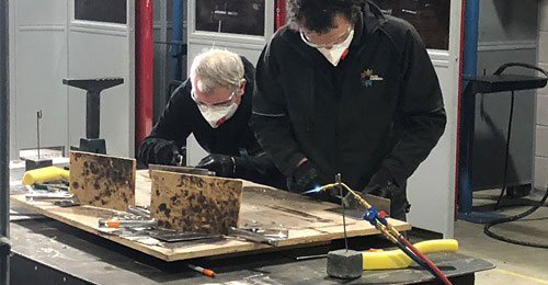
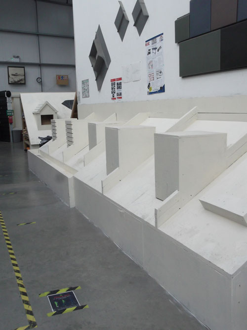
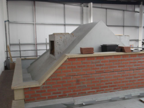
The Lead Sheet Training Academy claims to be the only training facility in the UK to be City & Guilds accredited for courses in Lead & Hard Metals.
I’ve always believed that good quality Training is REALLY important, especially in this Day and Age. After all, who wants to employ a tradesman who can’t prove they have the skills! Not Me!
Oops! 😀
OK, so I’ve just realised this is starting to sound like a sales pitch for the Lead Sheet Academy, but I assure you it’s not. (The Welders Warehouse is not receiving any payment for this article). I just believe in banging the drum for organisations that help develop British Industry!
Lead Sheet Training Academy Courses
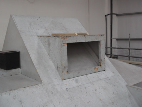
Numbers on courses are quite tightly controlled. On a “Basic” Course for example, numbers are limited to a max of 7, whilst the “Intermediate” course is limited to 6 max and the “Advanced” just 3.
This was great to hear as it means everyone on a course gets plenty of attention.
I remember when I did my apprenticeship in the late 70’s/early 80’s, being in a class of 15, which meant I spent most of the workshop time unsupervised. A Teenager, unsupervised, with an Oxy/Acetylene Gun!!!! Can you imagine that happening now 😀. I’m amazed we all lived 😂.
I hope you found this blog article/ramble about my visit to the Lead Sheet Training Academy interesting.
You can find out more on the Lead Sheet Training Academy website or give them a call, they’re nice people who I’m sure would love to talk to you!
Please let me know what you thought by leaving a comment.
Don’t worry, your email address won’t be added to a database or shared and you won’t receive any unsolicited email.
Cheers
Graham
Choosing a Mig Welder
You’ve decided you want to buy a Mig Welder, but discovered there’s a bewildering choice out there. So how do you go about
choosing a Mig Welder?
As not everyone is not a reader, I’ve also produced a video on this subject
First things First
It may sound a bit obvious, but the first thing you should consider when choosing a Mig Welder is what you want to be able to do with it!
There’s little point in buying a 150amp Mig Welder because it runs off a 13amp plug if you want to weld 10mm thick sheet steel – it’s simply not powerful enough.
Conversely, there’s little point in spending big money on a 300 amp machine if you only want to repair stuff at home and/or restore a classic vehicle.
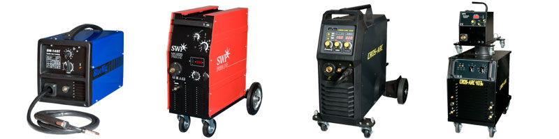
So power output and you own power supply are important considerations.
Broadly speaking, you can run a Transformer machine up to around 130 or 150amps (depending on machine), off a 13amp plug.
Inverter machines can be run at around 160amps off a 13amp supply. This is because an Inverter is more electrically efficient than a traditional transformer.
Having said all that, if you want to weld car body panel thickness material, the top end power is far less important than the bottom.
To weld car body panels you need a Mig Welder with a minimum output of no more than 30amps. A higher minimum output will result in lots of hole blowing in thin sheet!
So consider BOTH ends of the power range, not just the top!
The Basics of a Mig Welder
A Mig Welder can be broken down into two basic parts, a Power Supply and a Wire Drive System (inc Torch).
The Power Supply will either be a Transformer or Inverter (more about these later).
In my opinion, the more important consideration is the Wire Drive System, including the Torch.
I say this because after around 30 Years in welding, wire drive problems make up about 80% of the problems I’ve seen with Mig Welders. From DIY units to big Industrial units.
Duty Cycle
Another consideration regarding the power output of a Mig Welder is Duty Cycle. This is essentially how long the machine will run for before it overheats. If you want to do long welds at high power, a small DIY Mig is unlikely to be the right choice for you. But if it’s mostly small jobs, you shouldn’t have a problem.
I’ve written a separate blog article about Duty Cycle if you would like to know more. Ive also produced a video if you prefer to watch than read:
What to look for in a Mig Welders Wire Drive System
For me, when choosing a Mig Welder a decent sized Wire Drive Motor is very important. Many units, especially in the DIY market, have small, cotton reel sized motors that are only just powerful enough, assuming everything else is perfect.
Yeah, like everything’s always perfect, especially after a few Years use!!!
Next is the robustness of the Wire Feed Roller System. This is hard to qualify, but most practical people will know a good Roller System from a cheap crappy one when they look at it.
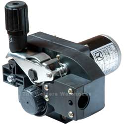
Mig Welder Torch
Lastly is the torch itself. A Steel Torch Liner is, in my opinion, VERY important. Many low cost machines have a plastic liner to cut cost. But this doesn’t last long when you’re feeding steel wire through it and changing the liner is usually a time consuming, fiddly job.
A plastic liner is also likely to be the No1 culprit of feed problems, and soon!!! So a torch with a steel liner is definitely worth looking out for!
A Steel Torch Liner looks like bicycle brake cable, a spiral of steel coated with plastic.
A really good thing to look out for is a Euro Torch. This Torch system has a Socket on the front of the Mig Welder and a Plug on the Torch.
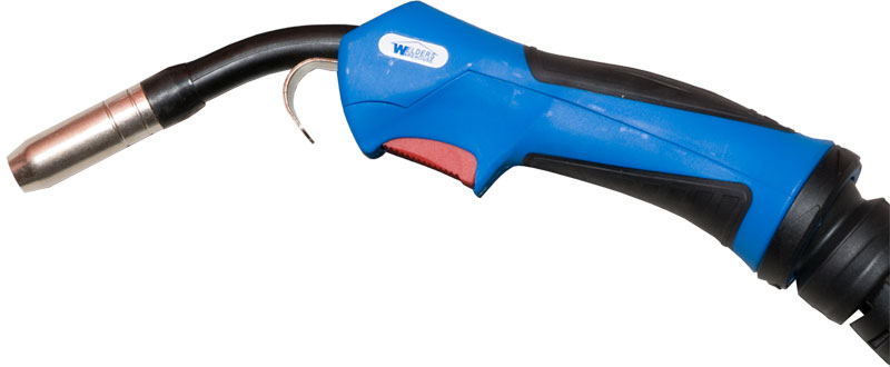
The Torch simply screws onto the Socket with a Hand Nut.
Euro Torches are better quality, yet are nearly always cheaper than the permanently fitted type (should you ever need to replace the torch). This is because Euro Torches are standard on Industrial machines and so are made by the Millions.
Permanent fit torches are usually bespoke and so have to be bought from the machine manufacturer. This can mean BIG money!!
I would expect all Euro Torches to be fitted with a Steel Liner, ours certainly are!
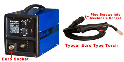
Types of Mig Welder
There are two basic types of Mig Welder, which is mostly about the type of Power Unit inside the machine. When Choosing a Mig Welder, this is a pretty fundamental choice!
Transformer Mig Welders
Transformers are the traditional power unit for a Mig Welder. The advantages of a Transformer based unit are that they are usually cheaper and less complex, so theoretically more reliable long term.
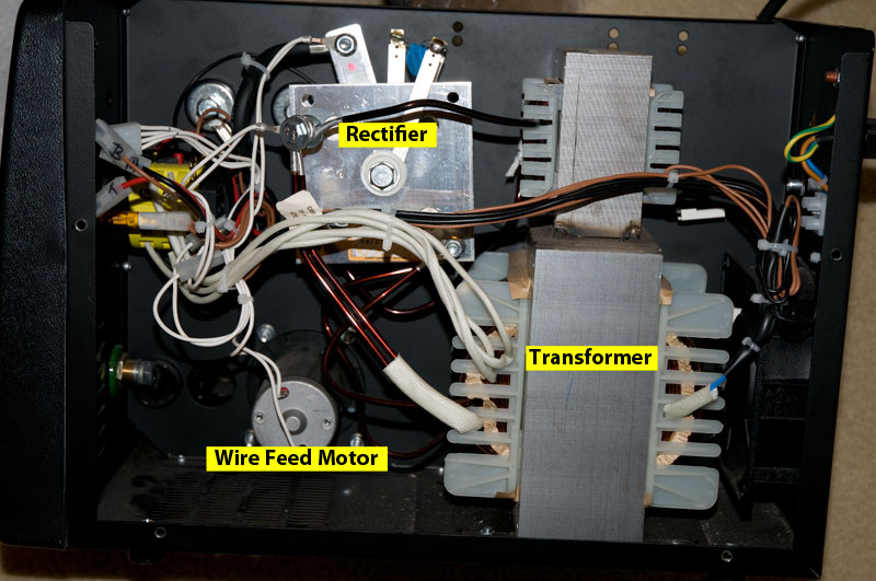
The downsides of Transformers are that they are Heavy, Overheat more quickly and the power output is usually set in a range of steps. Transformer Mig Machines typically have between 2 and 30 steps. It is not possible to set a power output in-between these steps.
From 1st January 2023 manufacturers will no longer be allowed to manufacture, or import, Transformer based Welders of any kind into the UK or EU.
Inverter Mig Welders
Modern inverters are also far more reliable than units of only a few Years ago. Another advantage is that power output is steplessly adjusted, in other words, power can be adjusted in the same way you would adjust the volume of a radio, simply by rotating a knob.
Inverters are a modern, electronic unit for a Mig Welder. The advantages of an Inverter based unit is that they are lighter, so easier to move around and will run for much longer before overheating.
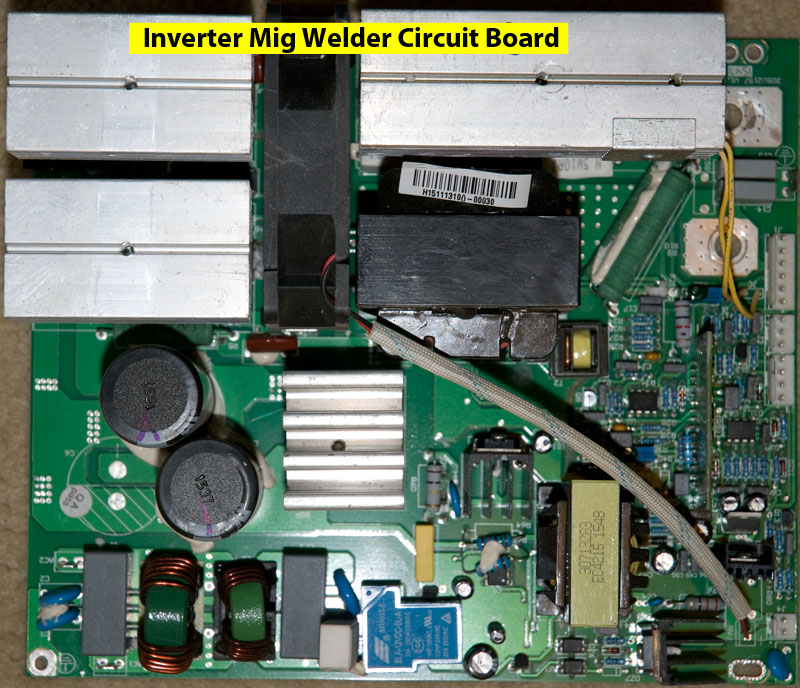
The only real, possible, downside with inverters is the complexity of an electronic board, which if it fails outside of warranty will need to be replaced. Replacement Inverter boards are not cheap as they typically represent over half the Mig Welders internal parts.
Conclusion
Which type of Mig Welder is right for you is a personal decision, because, as we’ve said, it all depends what you want to be able to achieve.
Visit our Mig Welders Page to view our current range.
Need to Know More?
If you need help and advice with choosing a Mig Welder, please don’t hesitate to get in touch. Either via the Contact Us page of our website, or by picking up the phone for an informal chat, ask for me!
I hope you found this article useful.
Please let me know what you thought of this article by leaving a comment.
Don’t worry, your email address won’t be added to a database or shared and you won’t receive any unsolicited email.
Regards
Graham
Gas Vs Gasless Mig Welding
Gas vs Gasless Mig Welding, which is best? is a conversation I have with customers on the phone on an almost daily basis.
Gasless Mig Wire
Firstly, let me clarify that “Gasless” Mig is not actually gasless. There’s no such thing as gasless mig welding. The weld pool has to be protected from the oxygen in the air and this is done by displacing the air with gas!
So called “Gasless” Mig Wire is actually “Self Shielding”.
Self Shielding Mig Wire is a tube of metal with a flux core.
As the welding arc melts the wire it also burns the flux, this produces a gas shield around the welding process. So NOT “Gasless”.
The term “Gasless” comes from the fact that Self Shielding Wires do not require a Cylinder of Gas.
Secondly, I’m going to put my cards on the table! I’m not the Worlds biggest fan of Self Shielding Mig Wire!
OK so it has its uses, but it produces a fierce arc that’s not much use on steel thinner than around 1.2mm.
As for car body welding, if a supplier tells you their machine can weld car body thickness steel without gas GET THEM TO DEMO IT!!!
Self Shielding Mig Wires also produce a LOT of nasty smoke, so are best used in the open air. And that really is the only place I would advocate using self shielding wire. Even then, I would only use Self Shielding Wire when its too windy to use solid wire and gas!
A Little Bit of History
Self shielding mig wires were first developed in the USA for use on the vast prairie farms of the mid west. A small hand held mig welder was developed that would operate off a deep cell, 24v Tractor battery. This welder was part of a tool kit carried by the farmer and used to carry out on the spot repairs to gates etc out in the fields.
Self shielding mig wires found their way into the UK DIY welder market in the 1980’s, before disposable gas cylinders became available. At that time it was the only way retailers could sell Mig Welders to the DIYer.
Solid Wire + Gas
By far the most common and best way to use a Mig Welder is with solid wire and a cylinder of gas.
With this configuration, the Mig Welder pours gas over the weld pool as you weld, thus keeping Air/Oxygen from contaminating the weld.
Solid Wire + Gas is easier to use and produces better quality welds
I’ve written a separate Blog article called:
Mig Welding Gas which you may find useful
Bottom Line
In my opinion, if you have a Gas/No Gas Mig Welder you should always use it with Gas, unless you absolutely have to use self shielding wire.
I personally, would prefer to protect the work area from wind with screens etc than use self shielding wire, but as I said earlier, I’m not a fan ?
We offer a full range of Mig Welding Wires for most materials, including Solid and Self Shielding wires for steel.
Can any Mig be used for Gas AND Gasless Welding?
No, a Mig Welder will be designed to either use Wire with Gas, Self Shielding (gasless) Wire, or both (Gas/No Gas).
The difference lies in the Polarity of the Torch.
To use Self Shielding (Gasless) wire, the Torch needs to be NEGATIVE (-).
To use Solid Wire with Gas the Torch needs to be POSITIVE (+).
A machine that can operate with both Solid Wire + Gas AND Self Shielding (gases) wire will have a way of quickly and easily changing the Polarity. These machines are normally marketed as “Gas/No Gas” Mig Welders.
Conclusion
Gas vs Gasless Mig Welding, which is best? Well I think you know my answer to this, Gas, almost every time! 🙂
Visit our Mig Welders Page to view our current range.
Need to Know More?
If you’re not sure what type of Mig Welder would best suit your needs, get in touch, you can write via our Contact Us page, or phone and ask for me! (numbers at the top of this page)
I hope you found this useful.
Please let me know what you thought of this article by leaving a comment. Don’t worry, your email address won’t be added to a database or shared and you won’t receive any unsolicited email.
Regards
Graham
Synergic Mig
What is Synergic Mig?
The Dictionary definition of “Synergic” is:
“Working Together Towards a Common End”.
A Synergic Mig Welder where Welding Power (Voltage) and Wire Feed Speed are adjusted together, rather than separately, via a single Control.
Most commonly, you pre program the machine with the size Mig Welding Wire being used, the type of Welding Gas being used and sometimes the type of metal being welded.
With this information, the machine sets itself up with ideal parameters for welding. All that’s left for the operator to do is set the power output for the thickness of metal being welded.
In most cases, the adjustment that’s being made is to the Wire Feed Speed; the machine’s Synergic Program then sets the Welding Power Output to suit. So if you need more power, you simply increase the Wire Feed Speed and the machine increases the Power Output to suit.
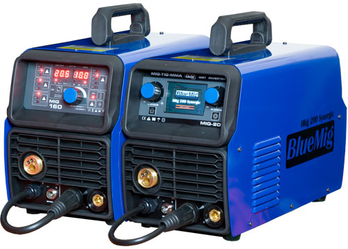
Advantages of Synergic Mig
- Easy to set the machine up
- REALLY easy to adjust power (one control)
- Good Welds are easily achieved because the Synergic Program takes all the guess work out of balancing the Power and Wire Feed Speed.
- If necessary, the balance between Power and Wire Feed Speed can be changed from the machine’s default.
- Most machines have an easy to read Control Panel, so checking the set up is really easy.
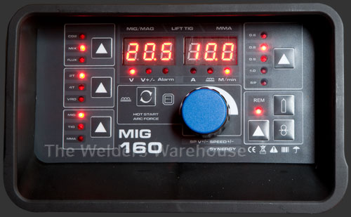
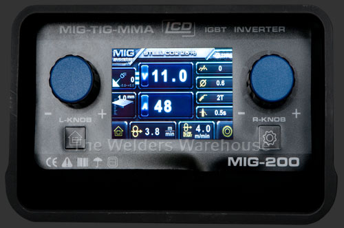
Synergic Mig Applications
You can get Synergic Mig Welders in a huge range of sizes and with a huge range of potential features.
At the straightforward end of the market Synergic Migs have become hugely popular with Maintenance Workshops, Sheet Metal Workshops, Vehicle Repair Workshops and Home/DIY Workshops. This is mainly because of how easy it is to get good results on straightforward welding applications.
At the high end of the market, machines can Pulse Weld, Double Pulse Weld, make Tea and update your Social Media (I might have made those last two up 😀). But these sort of machines cost Thousands and are for specialist Industrial applications.
Conclusions
Synergic Mig creates a Synergy between Power & Wire Feed Speed that means they’re “Working Together Towards a Common End” in our case, producing a great weld!
You’ll find Synergic Mig is easy to set up and easy to achieve great results with the minimum of skill and experience of Mig Welding.
Once you’ve used a Synergic Mig Welder, you’re unlikely to want to go back to a conventional Mig Welder!
I hope you found this blog article useful.
Please let me know what you thought by leaving a comment.
Don’t worry, your email address won’t be added to a database or shared and you won’t receive any unsolicited email.
Cheers
Graham
10 Tips to Improve your Mig Welding
Mig Welding is not a difficult process to master, but unless you get the basics right, it can be torturously frustrating! These 10 Tips to improve your Mig Welding help.
- Ensure your Mig Welder is in good working order; by that I mean making sure the Torch and Work Return (Earth), lead connections are clean and good. Make sure the Torch end parts are in good condition. Also check the Work Return (Earth) clamp is in good clean condition.
- Check your Welding Wire is in good condition, if it’s rusty or dirty you should pull off the imperfect wire and discard it, because poor quality wire will lead to poor quality welds!
- Check your Welding Wire Spool turns easily on the Spool Holder. It should have a little friction so it doesn’t overrun when the motor stops pulling the wire, but it shouldn’t be stiff to turn. Some spool Holders are adjustable, some are not. All can get dirty and cause jamming, so make sure the Holder is clean so the Spool turns smoothly.
- Check you Wire Feed Rollers are clean and in good condition, because Rollers in poor condition will lead to erratic wire feeding and therefore poor quality welds. The Tension of the Rollers is VERY important. I’ve written a separate article on How to Adjust Mig Welder Wire Feed Roller Tension and produced a Video (bottom of linked page), do please check these out.
- Ensure you have the correct gas and gas flow rate. I’ve written blog articles on Mig Welding Gas and Gas Flow Rate for Mig
- Place your Work Return (Earth) Clamp onto one of the pieces of metal you will be welding. Ensure the Clamp faces are clean and the metal you’re clamping onto is clean, because this is an electrical connection that is part of the welding circuit, so a good, clean connection is important!
- Ensure the weld area of the parts to be welded are clean and free of surface contaminants, including rust, because if you weld over contaminants, they will end up in the weld!
- Angle your Torch at approximately 70⁰, pointing in the direction you are going to move. In other words, you need to Push the torch, NOT Drag it!
- Initially “Tack” the metal together with a short burst of welding, a tack every 50-75mm should be sufficient in most cases.
- When running the weld, move as smoothly as possible, I find either resting my torch arm on my other arm, or putting down a finger for steadying is a BIG help.
I hope you found this blog article useful, if things work out well for you, please feel free to post some pictures of your achievements on our Facebook Page
Please let me know what you thought of this article by leaving a comment. Don’t worry, your email address won’t be added to a database or shared and you won’t receive any unsolicited email.
Cheers
Graham
3 Easy Steps to Perfect Mig Wire Feed Speed
Mig Welders are relatively simple pieces of equipment and are easy to use, the key is getting the machine set up correctly in the first place. Key to this is the setting the wire feed speed correctly.
A lot of smaller machines on the market, BlueMig BM-150T for example, have a helpful Chart, indicating the settings most likely to suit a given thickness of metal with a given size of wire.
Example of Welding Chart
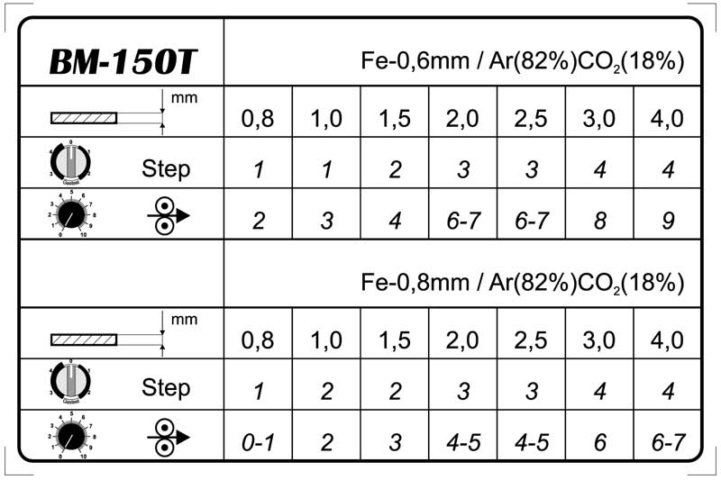
3 Steps to Perfect Wire Feed Speed
- Set the wire feed speed to a level that you know will be too high for the power output setting you’re using (this may be a best guess).
- Start an arc on a scrap piece of metal. With too much Wire the arc will “Stutter” and you will feel your torch bucking in your hand as the wire repeatedly hits the metal. If it doesn’t, increase the wire feed speed, whilst welding, until it does!
- Whilst maintaining this Stuttering Arc, SLOWLY reduce the wire feed speed. The Arc will suddenly run smoothly with an even “Crackle” and the torch will stop bucking in your hand.
CONGRATULATIONS, you now have the correct wire feed speed for the Power Output you’ve set on the machine and the size of wire you’re using.
Once you’ve got the setting right, it’s worth making a note of the setting for that wire and power output for future reference. Essentially, you start writing your own chart!!!
Conclusion
Getting the correct Wire Feed Speed on a Mig Welder is critical to getting a good quality weld.
Too much wire feed will generate a lot of spatter and a lack of penetration, not to mention a weld that looks like a line of Pigeon dropping 🙂
Too little wire feed will generate a weak flat weld, possibly with undercut.
Please let me know what you thought of this article by leaving a comment. Don’t worry, your email address won’t be added to a database or shared and you won’t receive any unsolicited email.
Cheers
Graham
How to Adjust Mig Welder Wire Feed Roller Tension
What is Roller Tension?
Mig Welder Wire Feed Roller Tension is how tightly the Rollers Grip the Mig Welding Wire to feed through the Mig Welders feed mechanism and torch. Feed Roller Tension is one of the more important mig welder settings.
As some of you may prefer to watch, rather than read, I’ve also produced a Video on this subject
Too Little Roller Tension
If the tension is too light the rollers can slip and wire will not be fed through at the correct speed, or will feed erratically, potentially causing the wire to burn back on to the copper Tip at the end of the Mig Welders Torch.
Too Greater Roller Tension
If the tension is too great, unnecessary strain is put on the Mig Welders Wire Feed Motor and there is a risk of damaging the surface of the Mig Welding Wire. If the surface of the wire is damaged, this can in turn damage the Mig Welder Torch Liner.
If the Mig Welder Wire Feed Roller Tension is too great on softer Mig Wires (e.g. Flux Cored & Aluminium), the wire can be slightly flattened, so instead of your welding wire being, say 1.0mm in diameter, it may become 1.1 x 0.9mm, this will then increase the risk of jamming at the copper Tip.
To Correctly Adjust the Tension
So how do your correctly adjust Mig Welder Wire Feed Roller Tension? Here’s the method that’s served me well with Home and Professional welders for the last 20+ Years:
- Ensure the Mig Welders Torch is COLD
- Feed out about 50mm of welding wire
- Reduce the roller tension until you can press the torch trigger and the rollers slip (wire does not feed)
- Grip the wire between your thumb and first finger. Your grip should be firm but not tight (no white knuckles please)
- Turn the tension adjuster ½ a turn
- While gripping the wire as described in 4, press the torch trigger, if the rollers still slip turn the adjuster another ½ turn and repeat
- What you want is to just about be able to stop the wire feed through your fingers, but without gripping hard!
Conclusion
Prevention is always batter than cure, but if you’ve already experienced the feed problems mentioned earlier, chances are you’re going to need to replace your liner. This is something you should do from time to time anyway as torch liners are a consumable. We carry a range of Mig Torch Spares and our website has a useful Torch Identifier to help you select the correct parts for your Mig Gun.
I hope you found this useful, if things work out well for you, please feel free to post some pictures of your achievements on our Facebook Page
Please let me know what you thought of this article by leaving a comment. Don’t worry, your email address won’t be added to a database or shared and you won’t receive any unsolicited email.
Cheers
Graham
Mig Welding Gas
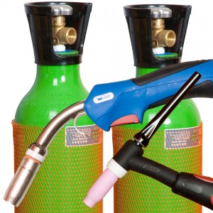
Mig Welding Gas is required because it’s essential to keep Oxygen from the weld pool.
Shielding gas does this by replacing the Oxygen containing air that’s all around the weld pool.
Categories of Mig Welding Gas
Mig Welding Gas falls into two basic categories, “Inert” & “Active”.
Inert means the gas has no effect on the welding process.
Active means the gas has some effect on the welding process (more on this later!)
Types of Inert and Active Mig Welding Gas
The most commonly used Inert gas is Argon. Argon is the main shielding gas used for Tig Welding and for Mig Welding Aluminium or Mig Brazing.
The most commonly used Active Mig Welding Gas is a mixture of Argon and Co2, although Pure Co2 is also still used.
Active gases are used for Mig Welding most metals (except Aluminium and Mig Brazing, where pure Argon is used).
Co2 is the lowest cost of the Active Gases, but is far from the best.
Co2 produces a cooler, coarser, more spattery arc and a marginally harder weld. Co2 is a more challenging gas to use on thin material and not all Mig Welders perform well with 100% Co2 as a shielding gas!
An Argon/Co2 mix produces superior results as the arc is softer and smoother with the resulting weld deposit slightly softer and more malleable than where pure Co2 is used.
There are several different mixes of Argon/Co2 on the market, typically:
95% Argon + 5% Co2, is ideal for Mig Welding up to around 10mm Steel
90% Argon + 10% Co2, is ideal for Mig Welding 8-25mm Steel
80% Argon + 20% Co2, is ideal for Mig Welding 20mm plus Steel
What Inert and Active Mig Welding Gas Does
An Inert gas, such as Argon, has no effect, or reaction, on or with the welding process, it simply performs the essential task of replacing Air/Oxygen from around the weld pool.
Active gases do have an effect on the welding process. The effect of an active gas on Mig Welding is twofold:
Firstly, the Co2 content in an Argon/Co2 mix makes the gas slightly electrically conductive, this in turn raises the arc voltage, which increases penetration.
The second effect is the Co2 content breaks down the surface tension of the molten weld pool (this is the same type of surface tension that allows water to form a drip).
Using Co2 to break the surface tension of the molten weld pool allows the weld to flow and flatten slightly for the correct weld profile.
If an Inert gas is used for Mig Welding (except Aluminium and Mig Braze), higher machine power output will be needed to achieve penetration and the finished weld will look too tall because the surface tension has not been broken.
Mig Welding & Mag Welding
The use of Active Gases for most Mig Welding applications means that most operators are actually MAG welding (Metal Active Gas) rather than MIG (Metal Inert Gas) welding, however, MIG has become the generic term, despite, in fact, being inaccurate
Mig Welding Gas Cylinders
Mig Welding Gas Cylinders in the UK can be obtained in three ways:
- Disposable Cylinders which are low cost to start out with and highly portable
- Deposit based Refillable Cylinders are more expensive to initially acquire as a deposit is required, but cheaper over the longer term as the gas fills are cheaper than using disposable cylinders.
- Rental Refillable Cylinders – here the cylinder is rented from the gas company, so there’s no deposit to pay. Ongoing gas fills are usually cheaper, but overall, cylinder rental is only cheaper for higher volume gas users where the lower gas fill cost compensates for the ongoing cylinder rental cost.
I hope you found this useful, if things work out well for you, please feel free to post some pictures of your achievements on our Facebook Page
You might also find my articles on Gas Flow Rate for Mig and No Rent Gas Cylinders useful.
Please let me know what you thought of this article by leaving a comment. Don’t worry, your email address won’t be added to a database or shared and you won’t receive any unsolicited email.
Cheers
Graham
What is the best gas for Mig welding mild steel
What is the best gas for Mig welding mild steel is a frequent question I get asked on the phone.
Unfortunately, there’s not a simple, straightforward answer as it rather depends on a number of factors!
The three key factors are:
- What’s your budget
- Do you want to use Disposable or Refillable Gas Cylinders
- What thickness of mild steel are you typically welding
I guess you can combine 1 & 2.
Disposable Gas Cylinders
If you’re using Disposable Gas Cylinders, you’re going to have a choice of Pure Co2, or an Argon/Co2 Mix. The Mix is typically 86% Argon 14% Co2.
In this instance, the Argon/Co2 Mix will produce nicer, more malleable welds, with less spatter. However, Argon/Co2 works out more expensive because the cylinders don’t last as long!
Pure Co2 will be a bit fiercer and more spattery to use, but the cylinders last longer, so the cost per minute of welding is less.
I often speak to customers who are mig welding on car restoration projects. My advice to them is always to use Argon/Co2 for visible areas of the car and Co2 for the non visible areas (floors, sills etc). This way you get better quality where you need it and lower cost where quality is not really an issue.
View our Disposable Gas Cylinders
Refillable Gas Cylinders
This is where the waters get a little muddier because there is a lot more choice of gas with refillable cylinders!
Pure Co2 is still a simple option. Some welders manage to blag Co2 cylinders from a friendly pub landlord and if you’re happy with the weld quality, well done you for getting what’s probably the lowest cost option.
For those wanting the better quality Argon/Co2 there are a range of mixes that are typically available.
- 95% Argon + 5% Co2 – I would use this for mig welding thin sheet and up to around 8-10mm thick Mild Steel.
- 92% Argon + 8% Co2 – I would use this for mig welding 3mm to 15mm mild steel.
- 90% Argon + 10% Co2 – I would class this as the same as the 92%+8%
- 80% Argon + 20% Co2 – I would use this for mig welding all thicknesses above 10mm.
For most DIY Mig Welding, the 95% Argon + 5% Co2 would be my pick!
The other advantage with Argon/Co2 is you can get away with using it for Mig Welding Stainless Steel. Industrial users tend to use more exotic gases for Stainless, but for the DIYer, Argon/Co2 is OK.
I’ve written a separate blog article about No Rent and Disposable Gas Cylinders that you might also find useful!
So what is the best gas for mig welding mild steel?
In my opinion, a 95% Argon + 5% Co2 will do pretty much everything a DIYer or Light Fabricator might want to do with a Mig Welder.
I hope you found this blog article about what is the best gas for mig welding mild steel useful.
You might also find my articles on Mig Welding Gases and No Rent Gas Cylinders a useful read!
Please let me know what you thought of this article by leaving a comment.
Don’t worry, your email address won’t be added to a database or shared and you won’t receive any unsolicited email.
Cheers
Graham
Gas Flow Rate for Mig
What’s the right Gas Flow Rate for a Mig is a question we get asked a lot, but like many things in welding, there’s no definitive answer.
The correct Gas Flow Rate for a Mig will depend on a number of factors:
- The diameter of the Gas Shroud
- The joint configuration
- Whether there is any uncontrollable factors that may disrupt the gas shield around the weld, draught/wind being the most obvious
Having said all that, I understand you need a start point, so I’ve produced a simple chart showing suggested Gas Flow Rate for a Mig.
This is based on a formula of the cross sectional area of the Gas Shroud Bore divided by 13.
For Example, let’s assume the Gas Shroud Bore is 10mm.
Cross Sectional Area (as I’m sure we all remember from school Maths :-), is
π x r² so:
π (3.142 is close enough) x 5 x 5 ÷ 13 = 6.042
We can round that to 6 litres per minute Gas Flow Rate for a Mig with 10mm bore Gas Shroud.
I would stress that this figure is a start point. Try a test weld, if you see tiny pin holes in the surface of your weld, you need more gas, but in still conditions, this formula should provide enough shielding without wasting gas by using more than necessary.
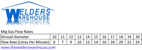
I hope this helps
If you would like a higher resolution copy of the chart, use the “Contact Us” link on our website to drop me a note and I will email you a copy.
You might alos find my articles on Mig Welding Gas and No Rent Gas Cylinders worth a read!
Please let me know what you thought of this article by leaving a comment. Don’t worry, your email address won’t be added to a database or shared and you won’t receive any unsolicited email.
Cheers
Graham
Can you use the same Gas for Mig and Tig
I get asked “can you use the same gas for Mig and Tig” a LOT!
Sadly, the answer is NO.
Gas for Mig Welding
Both Mig and Tig Welding require gas to protect the weld pool from Oxygen and often to cool the Torch but these are not the only functions it performs with Mig Welding.
First off, “MIG” which stands for “Metal Inert Gas”, is actually an incorrect term. This is because virtually all gases used for Mig Welding are “Active” gases, so it should be called “MAG” welding, or “Metal Active Gas”
North American’s get around the Mig/Mag issue by calling the process “Gas Metal Arc Welding”, or GMAW).
Anyway, MIG welding (we’ll use the popular term), uses mostly Active gases, usually a mixture of Argon (Inert) and Co2 (Active).
“Inert” means the gas does not react with anything, “Active” means the gas does react with, or changes something else.
An Active gas is used with Mig Welding for two reasons:
- The Active Gas mixes make the gas semi conductive to electricity, makes for a hotter arc and better penetration.
- The Active Gas breaks the surface tension of the molten metal, allowing it to flatten out more.
Using an Inert Gas like pure Argon will result in the machine needing to be turned up higher and the welds will be taller.
Pure Argon should only be used for Mig Welding Aluminium, or for special applications.
I’ve written specific articles on Mig Welding Gas and No Rent Gas Cylinders that you might find useful!
View our range of Disposable Gas Cylinders
Gas for Tig Welding
Whilst there are some more exotic (and expensive) mixes available, most welders will find pure Argon to be ideal for Tig Welding most metals.
Gas for Tig Welding is to protect the weld pool from Oxygen and to Cool the Torch, unless a Water Cooled Torch is being used.
If you use an Active Gas for Tig Welding, you will find you will blow holes quite easily and the Tungsten Electrode will burn away very quickly.
View our range of Disposable Gas Cylinders
Conclusions
As we’ve found, you can’t really use the really use the same gas for Mig and Tig Welding. They are significantly different processes.
I hope you find my answers to the question “can you use the same gas for Mig and Tig” useful.
Please let me know what you thought of this article by leaving a comment.
Don’t worry, your email address won’t be added to a database or shared and you won’t receive any unsolicited email.
Cheers
Graham
Welding Aluminium with Mig
Firstly, Mig Welding Aluminium with a general purpose Mig Welder is not ideal, a DIY type machine is even less suitable.
The best type of machine to weld Aluminium with is an AC/DC Tig Welder
Having said that, with the right set up, most Mig Welders can be used for welding aluminium (more or less), provided they’re set up correctly.
The challenges of Mig Welding Aluminium
Mig Welding steel is not difficult, this is because when it comes to setting the machine up:
> Roller Tension
> Torch Liner Quality
> Power Setting
> Wire Feed Speed
there is a reasonable margin of error.
For example, if your wire feed speed is a little High, or Low, you’ll get away with it. If you’re trying to weld Aluminium you WON’T get away with it. Wire feed speed that’s too low will cause the wire to burn back on to the Tip, too high and it will hit the job, potentially causing a “Birds Nest” of wire inside the machine! All very frustrating.
For Mig Welding Aluminium, you will need:
> Pure Argon Gas, NOT Co2 or an Argon/Co2 mix
> Plastic or Teflon Liner in your Torch (more on this later)
> An oversize Tip for the end of the Torch (more on this later)
> A Reel of Aluminium Wire suitable for the grade of Aluminium you intend welding
> LOTS of patience getting the Power and Wire Feed Speed right
Mig Torch Liner for Mig Welding Aluminium
A Regular steel liner (looks like bicycle brake cable), will scrape the surface of the Aluminium Welding Wire, causing the wire to bind/jam in the liner. A Plastic or Teflon Liner MUST be used to avoid this. If your Mig Torch already has a plastic liner, but you’ve been using it to weld steel, I would recommend fitting a new liner for Mig Welding Aluminium.
Oversized Mig Tip
Because Aluminium has binding properties, it may jam in a regular tip, especially when the tip gets hot. Some types of tip can be purchased in an “Aluminium” version, these are slightly oversized to compensate. If your machine’s tip type is not available in an Aluminium version, I would suggest using 1.0mm tip for 0.8mm wire.
Aluminium Mig Welding Wire
Several grades of Aluminium Mig Welding Wire are available and the grade selected needs to be compatible with the Aluminium to be welded.
If your welding a straightforward commercial grade of Aluminium, my suggestion would be to use a 5356 grade Aluminium Mig Wire You can use a 4043 grade, but this is a softer wire and therefore more prone to feed problems.
Setting up for Mig Welding Aluminium
OK, you’ve got Argon Gas, you’ve fitted a Plastic/Teflon Liner and oversized tip and you’ve fitted your spool of 5356 Welding Wire.
Next you’ll need to place close attention to the tension on your feed rollers. Ideally, you’ll be using ‘U’ shaped rollers, but if all that’s available for your machine is ‘V’ shape, these will have to suffice. Set the Roller Tension AS LOW AS POSSIBLE. Do this by starting at a point where the rollers slip and don’t feed the wire. Then slowly increase until the wire does feed OK. More info on Roller tension can be found in our Knowledge Zone
Power Setting
This will be determined by the job. If you’re an experienced welder of steel, start by setting the Power about 50% higher than you would for the same thickness of steel.
Wire Feed Speed
This will be determined by the job. If you’re an experienced welder of steel, start by setting the Wire Feed Speed about 100% higher than you would for the same thickness of steel.
Ambient temperature
If you’re doing a job in cold weather, try warming the job up a little. What you’re looking for is the job to not be cold to the touch, so if it is, put a fan heater on it for a few minutes. A job that’s warm to the touch will weld easier. This shouldn’t be necessary in Summer.
Getting Started – Patience Patience Patience
Make sure metal you intend welding is clean, running a sanding disc over the area to be welded can also help if the aluminium is old as this will reduce the effects of surface oxide.
Getting the balance of Power and Wire Feed Speed when trying to Mig Weld Aluminium is a frustrating exercise of trial and error.
Start by angling the torch at 45⁰ as this will minimise the risk of birds nesting wire inside the machine if the wire feed speed is too high.
Once you’ve got the Power and Wire Feed Speed set correctly the process is not dissimilar to welding steel. Hold the torch at around 70⁰, and move slowly along.
I hope you found this useful, if things work out well for you, please feel free to post some pictures of your achievements on our Facebook Page
Please let me know what you thought of this article by leaving a comment. Don’t worry, your email address won’t be added to a database or shared and you won’t receive any unsolicited email.
Cheers
Graham
Mig Wire Feed Problems
Mig Wire Feed Problems can come in a range of guises, all of them annoying!
Mechanical Mig Wire Feed Problems
Mechanical problems with the Wire Feed system are by far the most common cause of issues with a Mig Welder!
My philosophy with these is to start at the Wire Spool end and check through EVERYTHING, even if you find a problem early on, still check everything else because there may be more than one issue!
Here are some suggestions and fixes:
Common Mechanical Wire Feed Problem Causes & Fixes
- Mig Wire Spool not turning smoothly
Depending on the type of Spool Hub your Mig Welder has:
In the case of an Industrial type Spool Hub. The wire spool not turning smoothly can be because the spool brake is too tight.
In the case of a DIY type Spool Hub. It may be that the Spindle the Wire Spool turns on has become badly worn, or dirty. It may also be that the Wire Spools label is catching on the Hub as the Spool turns! - Mig Spool Overruns spilling wire into the machine
If you have an Industrial type Spool Hub it’s most likely the Spool Brake is too loose. You will need to tighten it enough so the Wire Spool stops as soon as the Feed Motor stops, but not so tight that the Feed Motor struggles to turn the Wire Spool.
If you have a DIY type hub, you may have lost the spring that provides tension on the Wire Spool. - Mig Wire is Jerky coming off the Spool
This may be a poorly wound spool of wire, try manually pulling the wire through your Torch and see if the wire is still jerky coming off the spool. If it is a poorly wound spool there’s not a great deal you can do about it. They sometimes get better as you use the wire, otherwise, you might need to change the spool for a better one!
- Feed Rollers Slip
There are quite few possible reasons for this:
a) You may be using the wrong sized groove for your wire, check this!
b) The Roller may be worn, in which case you will need to replace it.
c) The Roller Groove may be dirty and part filled with fine metal dust, clean it thoroughly!
d) The Spool Brake may be too tight (as discussed above).
e) There maybe problems further down the line, which we’re coming to! - Feed Roller Tension
If the Feed Roller Tension is too high, the Mig Wire can be distorted, especially if you’re using Flux Cored (Gasless) Wire!
Feed Roller Tension that’s too high can flatten the wire a little so that instead of being say 0.8mm diameter and round, it becomes 0.7mm x 0.9mm and Rugby Ball shaped. You’re then trying to push a 0.9mm wide wire through a Mig Tip in the end of your Torch that was made for 0.8mm wire!
I’ve written a separate blog article on Feed Roller Tension and produced a video if you prefer to watch rather than read. - Guide Tube Blocked
Mig Welders with Euro Type Torches have a Guide Tube between the Feed Rollers and Torch.
This Guide Tube is typically around 4-5mm in diameter and sharpened like a pencil at both ends.
Over time, metal dust can build up in the guide tube, causing the wire to part, or fully, jam.
Remove the Guide Tube and either replace, or clean thoroughly so wire passes through unimpeded. - Blocked or Damaged Torch Liner
Torch Liners are usually either Plastic, or Metal.
Plastic Liners wear very quickly, so if wire feed problems are caused by the Torch Liner, a plastic liner will need to be replaced.
If your Torch Liner is metal (looks like bicycle brake cable coated in plastic), it may have become partly blocked by copper dust from the Mig Wire. This can usually be resolved by removing the Copper Mig Tip at the end of the torch and blowing the Liner out from both ends with an Airline.
If blowing the liner out doesn’t cure the problem, remove the liner and check it’s not kinked, if it is, it will need to be replaced.
Some DIY Mig Welders have a small additional liner in the Torch Neck. These are often only fitted to torches that have a Gas Valve built into the torch handle. If you have one of these, also check this. - Mig Tip in poor condition
The Copper Mig Tip at the end of your Torch is what transfers welding current onto the wire, so it’s important it’s in good condition.
Check you have the right size of tip for the wire size you’re using!
The Mig Tip can become worn and/or blocked. This can cause the wire not to feed through it very well and/or lead to poor transfer of welding current from machine to wire. This in turn can cause the arc to “stutter”, which can be misinterpreted as a wire feed problem.
If the condition of the tip is in any doubt, replace it to eliminate this as a possible cause of problems! - Too Little Gas Flow
We all know the main reason for using gas is to protect the weld pool from oxygen in the air. However, the shielding gas also provides “Gas Cooling” for the end of the Mig Torch.
If there is insufficient Gas Flow, the Mig Tip can become very hot.
When metal gets hot it expands. As the metal expands, the hole through which the wire is feeding gets smaller, potentially causing the wire to then jam.
A key pointer to this being the problem is if wire feeds OK when you first start welding and the end of the torch is cold, but becomes problematic as the torch parts get hot!
This is also more likely to be a problem when using flux cored (Gasless) wire!
Conclusions
Most Mechanical Wire Feed Problems are pretty simple to fix. It’s all about being systematic and as I said at the start, don’t stop checking when you find a problem because it might not be the only one!
I’ve been fixing Mig Welders, Industrial and DIY for the best part of 30 Years and Mechanical Wire Feed Problems make up the majority of issues I’ve had to fix for customers.
I hope you found this article useful.
You might also find my article 10 Tips to Improve your Mig Welding useful.
Please let me know what you thought of this article by leaving a comment.
Don’t worry, your email address won’t be added to a database or shared and you won’t receive any unsolicited email.
Regards
Graham
Weld Preparation
For most things in Life, preparation is important, Weld Preparation is no exception.
There are some fairly obvious weld preparations
- Make sure the metal to be welded is free from grease or paint.
- Make sure the metal to be welded is free from rust or other corrosion.
- Try to place your Work Return (Earth) Clamp on one of the pieces of metal to be welded, rather than another part that’s joined to the parts to be welded (doesn’t apply to Gas Welding).
Where thicker metals are to be welded, a joint preparation may be needed.
Butt Weld Preparation
Typically, this would involve creating a ‘V’ preparation by grinding a chamfer onto each piece of the joint.

A 60º Chamfer is ideal, but you don’t need to get over precise with it.
As a Guide, “s” should be around 2mm, or 1/3 of the metal thickness, whichever is the lesser.
As a Guide “g” should be around 0.5mm for metal up to around 2mm thick, then around 1/4 of the metal thickness for metal from 3-10mm thick.
Fillet Weld Preparation

Fillet Weld Preparation is a little simpler. Here I would make sure the upright piece of metal has nice sharp corners where it meets the flat piece of metal.
The reason for this is it’s easier to get good penetration if the corner of the upright is nice and sharp. A radius on the corner will mean the arc will need to burn in deeper to create good root penetration.
Why Clean Metal is Important
Firstly, attaching your Work Return Clamp (Earth) to clean metal is important because you need a good electrical contact for Arc Welding processes (Mig, Tig, MMA).
Secondly, surface contaminants like Rust, Grease and Paint will vapourise under the extreme temperature of the welding process.
Vapourised contaminants can then bubble up through the weld and get trapped as the weld solidifies. This leaves bubbles trapped in the weld (a bit like Aero chocolate), weakening the finished weld.
Vapourised contaminants will also create nasty fumes that can be particularly hazardous if breathed in!
Conclusions
Weld Preparation is important, so shortcuts should be avoided.
Clean metal is important for both finished weld quality and your health!
I hope you found this blog article about Weld Preparation useful.
Please let me know what you thought by leaving a comment.
Don’t worry, your details won’t be added to a database or shared and you won’t receive any unsolicited email.
Cheers
Graham
How Much Wire is on a Mig Spool
I regularly get asked “How Much Wire is on a Mig Spool”, so I figured it was time I posted some figures 😀
0.6mm
- 0.7Kg (1.5lb) Mig Spool = 350M (1148ft)
- 5Kg (11lb) Mig Spool = 2502M (8209ft)
- 15Kg (33lb) Mig Spool = 7506 (24625ft)
0.8mm
- 0.7Kg (1.5lb) Mig Spool = 194M (636ft)
- 5Kg (11lb) Mig Spool = 1387M (4550ft)
- 15Kg (33lb) Mig Spool = 4161 (13651ft)
1.0mm
- 0.7Kg (1.5lb) Mig Spool = 125M (410ft)
- 5Kg (11lb) Mig Spool = 894M (2933ft)
- 15Kg (33lb) Mig Spool = 2682 (8799ft)
1.2mm
- 0.7Kg (1.5lb) Mig Spool = 85M (279ft)
- 5Kg (11lb) Mig Spool = 608M (1995ft)
- 15Kg (33lb) Mig Spool = 1824 (5984ft)
All of the figures are based on weighing a sample length of Mild Steel Mig Wire to calculate how much wire is on a Mig Spool.
Figures for Stainless Steel Mig Wire will be similar.
Visit our Mig Welding Wire Page to view our range.
I hope you found this blog article about How Much Wire is on a Mig Spool useful.
Please let me know what you thought by leaving a comment.
Don’t worry, your email address won’t be added to a database or shared and you won’t receive any unsolicited email.
Cheers
Graham
Fuzz Townshend – Car SOS
I first met Fuzz Townshend when he was a journalist at Practical Classics magazine and got involved in several projects with him including a Mig Welding project that saw Fuzz choosing one of our Mig Welders.
Since then, a few years have passed and now Fuzz co-presents Car SOS on Channel 4, where our Mig Welder is often seen, albeit in the background, well the show is about cars ?
A couple of weeks ago Fuzz got back on touch as he was seeking a Tig Welder for use in the next series of Car SOS. After a chat on the phone we decided the best machine for the job was the Cross-Arc 200 AC/DC
So Yesterday, my lovely Wife and I drove up to the Car SOS workshop in Oldbury, West Midlands, to deliver the machine and run through the basics of getting up and running with this excellent Tig Welder.
Fuzz and the guys intend to use the machine for some of the finer car welding work where the greater control and quality of Tig Welding can be exploited. Fuzz commented that “as some of the vehicles in the forthcoming shows have Aluminium bodies, the AC function of the Cros-Arc 200 AC/DC Tig Welder will come in very useful”.
For those who have not seen the show, the show synopsis is as follows:
“Overhaulin’ ” fans can relate to the premise of “Car SOS.” Both document the done-in-secret car restorations for needy or down-on-their-luck owners, with the main difference being the former show is based in the U.S. and the latter in the U.K. “Car SOS” is driven by hosts Tim Shaw and Fuzz Townshend, whose combined talents — Shaw is parts manager, and Townshend is master mechanic — rescue much-loved classics from rusty retirements. With some grease, graft, expertise and care, the SOS team creates jaw-dropping motor makeovers.
I appreciate this article is a little self indulgent, but I hope you still found it interesting.
Please let me know what you thought of this article by leaving a comment. Don’t worry, your email address won’t be added to a database or shared and you won’t receive any unsolicited email.
Cheers
Graham
Welding Stainless Steel
Welding Stainless Steel is no big deal. As long as you use a suitable welding rod or wire for the type of Stainless Steel you intend welding, all should be pretty straight forward.
Welding Stainless Steel is not vastly different to welding Mild Steel, which is why I say it’s no big deal, however, there are a couple of things worth noting.
- Stainless Steel doesn’t conduct heat as quickly as Mild Steel, so you normally need a little less power.
- Stainless Steel is more prone to distortion.
Types of Stainless Steel
I could write a book on all the different types of Stainless Steel, but for the purposes of this article I’ll stick with just the main two Austinetic Stainless Steels that most of us are likely to encounter.
- 304/304L – This is the most common “general purpose” Stainless Steel and is welded with one of the 308 spec Welding Rods or Wires.
- 316/316L – This grade is most commonly found in food related applications, industrial kitchen equipment for example and is welded with one of the 316 spec Welding Rods or Wires.
Types of Welding Rod or Wire
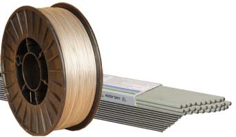
The general rule with Welding Stainless Steel is to weld it with either the same grade of Welding Rod, Tig Wire or Mig Wire, or a higher grade. So you could weld 304 Stainless Steel with a 308 or 316 Rod/Wire, but you shouldn’t weld 316 with a 308 Rod/Wire.
308 and 316 grades of Welding Rod/Wire are often modified from the basic alloy. These modifications are indicated in the basic spec number, for example, the most common is 308L & 316L, the “L” denotes Low Carbon. A lot of Mig and Tig Wire may be 308LSi & 316LSi, this denotes Low Carbon and added Silicon. Adding Silicon will make the molten weld metal slightly more fluid and so flow better.
Processes for Welding Stainless Steel
Stainless Steel can be welded with a Tig Welder, Mig Welder, or Stick Welder so lets look at the pros & cons of each.
- Tig Welding – This is the slowest process for welding Stainless steel, however, in the right hands, it will produce the nicest looking welds and because of its superior control, distortion can be better mitigated. Stainless Steel is Tig Welded with a Direct Current (DC) output.
Pro = Control/Quality
Con = Slow - Mig Welding – This is the fastest and, arguably, the easiest process for welding Stainless Steel and is ideal for production environments. Welds are unlikely to be works of art, but if that’s not important, Mig is a good option for most operators.
Pro = Fast and no harder than Mig Welding Mild Steel, no machine modification is needed, just a reel of Stainless Steel Wire and Argon/Co2 Gas.
Con = Not good for decorative welds. Limited control of distortion. - Stick Welding – welding Stainless Steel with a stick welder is as straightforward as Mild Steel; if anything, slightly easier, as the rods tend to run with a nice soft, smooth arc. Only thing to watch out for is the slag! This tends to fly off on its own and has a nasty habit of getting in your eyes. This is VERY painful (I speak from bitter experience 🙂 keep an auto helmet down, or wear safety glasses until ALL slag is removed.
Pro = No harder than stick welding Mild Steel
Con = Not as good as Tig for decorative welds and potentially dangerous slag removal.
I hope you found this useful, if things work out well for you, please feel free to post some pictures of your achievements on our Facebook Page
Please let me know what you thought of this article by leaving a comment. Don’t worry, your email address won’t be added to a database or shared and you won’t receive any unsolicited email.
Cheers
Graham
Are Automatic Welding Helmets Safe?
Are Automatic Welding helmets Safe? Your Eyes are, arguably, your most vulnerable and most important sense, so it’s important to look after them.
What’s the Hazard?
Arc Welding processes (Tig Welding, Mig Welding, Stick Welding, Plasma Cutting etc) emit a range of light wave lengths that are hazardous to eyes, including Ultra Violet (UV), which is the most dangerous to eyes.
“Arc Eye” is a common and painful hazard for Welders. Arc Eye is essentially the UV Burning of the back of the eye. This is exactly the same as Sunburn to the skin. A mild Arc Eye feels like sand in the eyes, severe Arc Eye is extremely painful and can lead to temporary, or even permanent blindness. Arc Eye also increases the risk of cancer in the eye.
Solutions
Traditional passive welding masks used a piece of shaded glass to reduce UV exposure. The darkness of this glass is typically 9EV to 13EV (13 being the darker). Maskss fitted with this glass are great for protecting the eyes from UV, but they’re so dark that the operator can see nothing until an arc is struck.
In the early 1990’s automatic welding masks came on to the market. These helmets are a bit like super fast, super dark, React to Light Sun Glasses.
When you’re not welding, the filter is a light green, allowing good vision for job set up and torch positioning. As soon as an arc is struck, the filter darkens to a welding shade. The welding shade can normally be adjusted, lighter, or darker.
When welding is finished, the helmet goes back to the Light Mode. This all happens VERY quickly! For example, our Speedshield V goes Dark in less than 1/10,000 of a second and comes back to Light Mode in between 0.2 and 1.0 second (user adjustable).

A question we get asked regularly is:
“Are Automatic Welding Helmets Safe, what happens if the mask does NOT darken when I strike an arc?”.
Well that’s where it gets a bit clever. All The Welders Warehouse Auto Welding Masks have a special coating that filters out UV to the equivalent of at least shade 15 glass. This coating is permanent, meaning you get shade 15+ protection from UV, even when the mask is in the Light Mode.
All this means that, provided you have the helmet down, there is ZERO risk of Arc Eye. The lightening and darkening of the Lens also means you don’t have to lift the helmet between welds or tacks to see where the next weld/tack needs to go, very convenient and great for productivity!
Are Automatic Welding Helmets Safe?
If you buy from a reputable supplier YES very safe!
Automatic Welding Masks are also easy to use, hugely convenient and productive.
You can see our full range of super safe, fully CE approved Auto Welding Masks on our website.
I hope you found this useful, please feel free to post some pictures of your achievements on our Facebook Page
Please let me know what you thought of this article by leaving a comment. Don’t worry, your email address won’t be added to a database or shared and you won’t receive any unsolicited email.
Cheers
Graham
Air Fed Welding Masks
February 2019 saw a “Safety Alert” from the Health & Safety Executive.
The notice reports on new Scientific Evidence that links Welding Fume exposure to Lung Cancer.
Click the “H&S Safety Alert” Text Link below to view, or Downloaded via the “Download” Button:
Welding Fume Protection
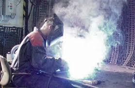
There is no single solution to Welding Fume Protection as it depends heavily on the environment where welding is carried out.
I’ve lost count of number of times a customer has told me that they keep the door open, or they only weld outside as justification for not having proper welding fume protection.
Dealing with Welding Fumes
In simple terms, you have to prevent Welders (and anybody else in the workshop), from breathing in Welding Fumes.
There are two basic ways of doing this: remove the fume at source to prevent it from reaching the welders Breathing Zone. Or protect the Welders Breathing Zone with a Respirator system.
Removing the fume at source means using Fume Extraction Equipment. Protecting the Welders Breathing Zone means using an Air Fed Welding Mask.
Fume Extraction
Fume Extractors come in a number of guises. The three most common are:
- Units with arms that are placed close to the welding
- Benches that suck fumes down into the bench.
- Special Mig Torches that have built in extraction.
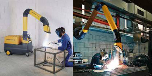
Fume Extractors use air suction to draw the fume away before it can rise into the Welders Breathing Zone.
Fume Extraction systems typically have a filter that filters out the harmful Particulate Fume and returns the cleaned air to the workshop. Some systems extract to the outside environment, but exhaust points are strictly controlled. After all, no one wants workshops protecting their welders by extracting the fume, only to pump it out onto the street where the public are walking by!!
The advantages of Fume Extraction at source include:
- Removal of Fume from the workshop, so other staff are also protected
- Low Maintenance – Filters need only occasional replacement
The alternative to Fume Extraction at source is to protect the welders Breathing Zone from the rising fume. An Air Fed Welding Mask, or PAPR system (Powered Air Purifying Respirator) is an excellent way to do this.
Air Fed Welding Mask
An Air Fed Welding Mask is battery Powered and worn on a belt around the welders waist. Air is sucked into the back of the Respirator Unit, through a Filter, then passed up to the Welding Helmet via a hose. This Air is then poured down across the Welders face. By creating this curtain of filtered air, which is further helped by a Face Seal, Fumes rising up from the weld do not enter the Welders Breathing Zone, inside the Welding Helmet.
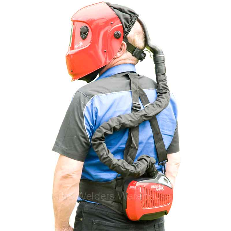
Air Fed Welding Helmet advantages include:
- Unit goes wherever the welder goes – He/She is wearing it!!
- In hot conditions, the air flow across the welders face has a cooling effect.
- An Air Fed Welding Mask is significantly cheaper than a Fume Extraction System.
Conclusion
The latest Health & Safety Executive “Safety Alert” is clear, action MUST be taken to protect Welders Lungs as well as anyone else who might be exposed to the welding fumes. Failure to do so is going to end up with much bigger problems, probably legal ones!
Please let me know what you thought of this article by leaving a comment. Don’t worry, your email address won’t be added to a database or shared and you won’t receive any unsolicited email.
Cheers
Graham
What does Duty Cycle mean in Welding
This is a common question. Essentially, Duty Cycle is a measure of how long a welder will operate for before it overheats and cuts out.
As some of you may prefer to watch than read, I’ve also produced a video on this subject
There are 3 key bits of data to Duty Cycle figures:
Amps, a Percentage Figure (%) and the Ambient Temperature the machine was tested in.
Unfortunately, whilst most manufacturers will state the first two figures, they often don’t state what the ambient temperature was when the test was carried out and this is actually a key piece of information! (more on this later).
An example of Duty Cycle data might be:
200amps @ 30% @ 40⁰C
This breaks down as follows:
200amps is what the machine was delivering during the test
30% is the percentage of the work period that the machine continuously delivered 200amps before overheating and cutting out. (in the UK a work period is defined as 10 minutes)
40⁰C (104⁰F) is the ambient temperature of the room when the test was carried out. So the machines fan is cooling the machine with air that is at 40⁰C
What do these Duty Cycle numbers mean?
In our example, the machine delivered 200amps, for 3 minutes (30% of 10 minute work period), in a temperature of 40⁰C, before overheating and cutting out.
Clearly these figures are pretty specific and hardly anyone is ever going to match all the numbers. For example, when is it ever 40⁰C here in the UK???? Clearly if the machine is being used in colder temps, the runtime (%) will increase. Which is why it annoys me that a lot of manufacturers don’t state the ambient temperature the test was conducted in.
Here in Europe, 40⁰C (104⁰F) is the norm, BUT this is not mandatory and some manufacturers will carry out tests in 25⁰C (77⁰F) or even 20⁰C (68⁰F), which, in my view, is a bit naughty because a lower temp will make the % figure look a LOT better than a machine that’s tested in 40⁰C (104⁰F). So beware!!!!!
Conclusion
The point of these numbers is to compare machines. It’s a bit like comparing car fuel consumption, no one ever gets the Miles per Gallon the manufacturers claim the car will do, but you can use the numbers to compare makes/models.
I hope you found this blog article useful, if things work out well for you, please feel free to post some pictures of your achievements on our Facebook Page
Please let me know what you thought of this article by leaving a comment. Don’t worry, your email address won’t be added to a database or shared and you won’t receive any unsolicited email.
Cheers
Graham